Building The Hardware
Building the hardware should not cause any problems for this is a very simple circuit. The layout is not extremely critical, so there are not many problems to be expected there. Naturally the crystal should be mounted as close to the micro controller as possible. And all the ICs should have a decoupling capacitor of 100nF connected to their supply pins as closely as possible.
 I have managed to squeeze the whole circuit in a plastic box measuring only 11.2 x 6.2 mm.
There was not very much room to spare in this box, but what use is there for free space anyway?
Of course you can reduce the size of the board even further if you use SMD type components.
But that causes problems with the Road-Runner wiring technique I'm using.
If you want to create a real PCB for this circuit you are likely to need some more space as it is hardly possible to put the components this close together with all the PCB tracks in between.
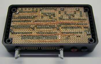
The picture shows you the rough layout of the main components on the PCB. You can somewhat simplify the wiring of the circuit by carefully arranging the IC's the way I did. Please mind the 1 pin displacement of some of the sockets in the picture and the orientation of the sockets. They were not placed like that by accident!
I placed 2 14-way DIL sockets head to tail to create one 28-way socket for the narrow package of the RAM IC. Most IC's are quite satisfied with normal quality sockets. Only the micro controller is best placed in a better quality socket. This was done because the micro controller had to be removed and re-inserted many times during program development.
Please note that the black and red RESET sockets occupy quite some space above the PCB where you can't put any components. Finally I used a 34 way boxed header with eject mechanism to connect the EPROM DIL connector to.
 Like always I used the Road-Runner wiring technique to build this project.
The signal lines are wired using a 0.15 mm² gauge insulated wire.
They are laid in small bundles underneath the IC's.
The power lines are 0.3 mm2 thick.
These power lines are also used to fix the wire bundles to their position.
Wires from an old transformer are also quite suitable for this purpose but mind the fumes when melting the insulation.
