The Hardware Part 1
 You can download the circuit diagram here.
It is spread over two sheets, one sheet covers the time base and the seconds, minutes and hours counters.
The other sheet covers the display circuit and the power supply.
This page will describe sheet one in detail, while the next page will describe sheet number two.
The download package contains the complete circuit diagram and the Bill Of Material, also known as the BOM. Together with this knowledge you should be able to build the clock yourself too.
As usual, with such a one of project, I didn't bother to create a PCB for the project. Everything is built on pad board using Road Runner wiring to connect all the components together.
The Buttons
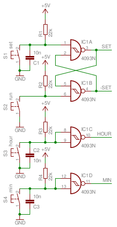
Let's start simple, the buttons, which are used to set the time. The clock can be in one of two different modes, in Run mode or in Set mode. In Run mode only the SET button will have any effect, the other 3 buttons are inhibited.
The SET and RUN buttons are used to switch between the two modes of operation.
It's no surprise that we use a traditional R/S flip-flop for that, which is built around IC1A and IC1B.
B.T.W. it is no error that S2 has no capacitor in parallel.
This way we force the initial state of the R/S flip-flop to the SET state after power up.
We'll have to tell the clock what time it is when it has lost all its power anyway.
Pressing the SET button will make the SET output go high and the SET output go low.
Pressing the RUN button will make the SET output go low and the SET output go high.
The HOUR and MIN buttons are used to increment the hours and minutes counters in set mode.
Both buttons have a debouncing capacitor in parallel to make sure that every button press results in just one pulse.
Every time the HOUR or MIN buttons are pressed a positive pulse is generated on the outputs of IC1C or IC1D for as long as the button is held down.
All button inputs are handled by Schmitt-Trigger NAND gates to make the slow rising signals purely digital again.
The Time Base
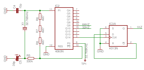
IC2 forms the time base oscillator and first pre-scaler stage.
The oscillator part is built as described in the HEF4060 data sheet.
It uses a 32.768kHz watch crystal as precision time base oscillator.
R6, R7 and R8 together form a 15MΩ feedback resistor since resistors of such a high value are a bit hard to come by.
I had a 12MΩ resistor in stock, which appeared to work perfectly too.
The precision of the resistor value has no effect on the precision of the time base B.T.W.
It is very important to use 0 tempco capacitor for C4.
This will increase the stability of your clock.
These kind of capacitors usually have a black line on top of their body.
TP1 is a test point at which you can measure the buffered 32.768kHz with a high resolution frequency counter. This helps to tune the frequency of the time base to the correct value. C5 is used to set the correct frequency.
IC2 also contains a 14 bit divider chain. At the end it will produce an accurate frequency of 2Hz on output pin 3. It also produces several other division ratios. We are only interested in two others, the 128Hz and the 64Hz outputs, which are used in the display section of the clock.
We need 1Hz, not 2Hz, to feed to our seconds counter.. Therefore IC3A is used to divide the frequency down to 1Hz. This signal is fed to the seconds counter, as described below.
The Seconds Counter
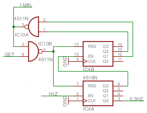
The seconds counter is built around a dual decade counter IC4A and IC4B.
IC4A divides the 1Hz pulse by 10.
IC4B tries to do the same for the 0.1Hz decade, but both counters are reset once this second decade reaches 6, which is every 60 seconds.
When the second decade reaches 6 the output of IC10A will go low.
This will produce a high going reset pulse on the output of IC10B.
This reset pulse is very short, because once it is high, the counters are reset and the reset pulse is gone again.
In my case the pulse was about 170ns wide.
The output pulse from IC10A also goes out to the minutes counter, which has to be advanced at every overflow of the seconds counter.
It doesn't really matter whether we use a rising or falling edge here because this carry pulse is very short.
In RUN mode the SET signal is constantly high, allowing the seconds counter to count the seconds normally.
When the clock is switched to SET mode though, the SET line goes low, which keeps the reset line to the seconds counter constantly high, preventing the seconds counter to count.
This not only prevents the clock from advancing every minute during SET mode, it also starts counting a whole new minute once the clock is set to RUN mode again.
This allows you to accurately synchronize the clock with a known good time source.
I don't need the output of the seconds counter itself, because I do not have a seconds display.
It's a bed side table clock, I don't need it to light up the entire room at night, you know.
There's one output we might use though.
It's output Q0 of the first decade counter IC4A.
This is a nice 0.5Hz output with a 50% duty cycle.
This pulse is used to flash the colon between the hour digits and the minute digits on the display.
The Minutes Counter
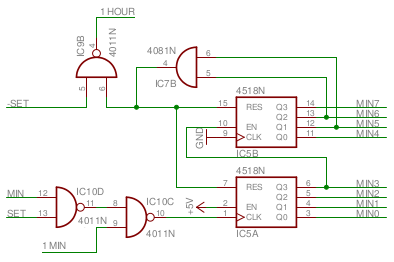
Next stop, the minutes counter. This counter is also formed by 2 decade counters. IC5A counts freely from 0 to 9, and when it overflows it advances IC5B. Once this second decade counter reaches 6 it will be reset back to 0 by the AND gate IC7B.
This reset pulse is also used as carry to the hours counter.
Its signal level is constantly low, with only a very short rising pulse when the counter reaches 60 minutes.
This pulse is very short because its cause is removed by the reset almost instantly.
IC9B is used to disable the minutes to hours carry while the clock is in SET mode.
Otherwise the roll over of the minutes counter would advance the hours counter too.
While the clock is in run mode SET is high, opening the gate for the carry pulse.
When the carry pulse goes high too, the output of IC9B goes low briefly.
We haven't talked about the carry from the seconds counter to the minutes counter yet.
In RUN mode the SET signal is low, which makes the output of IC10D always high.
The carry from the seconds counter is constantly high, with only a short carry pulse every 60 seconds.
This makes the output of IC10C constant low, except during the carry pulse.
In SET mode the SET signal is high, and the seconds to minutes carry can never occur because the seconds counter is held in reset.
When the MIN button is pressed the MIN signal goes high too.
Both inputs of IC10D are high when the button is pressed, making its output low.
Eventually the output of IC10C goes high when a button is pressed.
This way you can advance the minutes counter during SET mode by pressing the MIN button repeatedly.
The Hours Counter
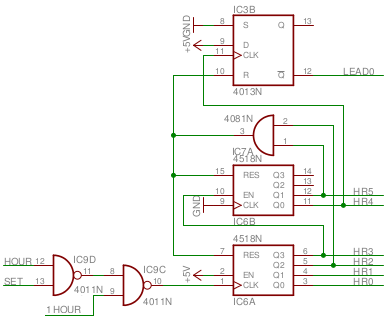
And now the hours counter. Again this counter is built around a dual decade counter, built around IC6A and IC6B. But this time the maximum count value is limited to 24. Fortunately 24 is a rather easy number to check, as it is the AND function between the HR2 and HR5 signals. Once the counters reach that state they are reset back to 0 again.
The carry into the hours counter is controlled by IC9D and IC9C.
Normally, when the clock is in RUN mode the output of IC9D is constantly high, because the SET input to that gate is low.
Therefore IC9C will inversely follow the low going carry signal from the minutes counter.
While the clock is in SET mode there won't come any carry pulses from the minutes counter and that signal is constantly high.
Now IC9D will inverse the pulses coming from the push button.
Each button press of the HOUR button will make the output of IC9D low, which then makes the output of IC9C high.
This allows you to advance the hours counter.
That's all.
Or is it?
What is IC3B doing there?
Let's see.
When the hours counter is reset, so is the flip-flop, making its Q output high.
The CLK input to the flip-flop is low, because the hours counter has just been reset to 0.
But when the most significant digit of the hours counter increments the clock input of the flip-flop rises, which sets the flip-flop, making the Q output low.
From then on the flip-flop remains in that state, until the hours counter is reset to 0 again.
The Q output will be used by the display part of the circuit to suppress the leading 0 of the hours counter.
I also could have used a NOR gate across the HR4 and HR5 lines to accomplish the same result a lot easier.
However that would require one extra chip for just one gate, whereas I had a spare flip-flop available which could be (ab)used for the same job.
OK, that's enough for this one page. As a matter of fact, there's no more on sheet number one to be explained. I have covered the time base and the counters here. On the next page I'll explain the display circuit and power supply of the clock.
