Before We Begin
 Before we can start doing any experiments we should refresh our own memory, or teach you some of the basics in case you are completely new to the MPF-1.
What are all those keys for?
What is the memory map of the computer?
How do I enter a program?
How to read and write our programs from/to tape?
What monitor routines can we use?
These are just some of the questions we should answer before we can start doing any experiments.
The Keyboard
Here's a brief description of all the keys on the MPF-1's keyboard, ordered to some degree of importance. For a detailed description you should read the chapter about the monitor.
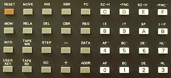
| Key | Function |
| 0 / AF | Hex digit 0 / Register AF |
| 1 / BC | Hex digit 1 / Register BC |
| 2 / DE | Hex digit 2 / Register DE |
| 3 / HL | Hex digit 3 / Register HL |
| 4 / AF' | Hex digit 4 / Register AF' |
| 5 / BC' | Hex digit 5 / Register BC' |
| 6 / DE' | Hex digit 6 / Register DE' |
| 7 / HL' | Hex digit 7 / Register HL' |
| 8 / IX | Hex digit 8 / Register IX |
| 9 / IY | Hex digit 9 / Register IY |
| A / SP | Hex digit A / Register SP |
| B / I.IF | Hex digit B / Register I & IFF |
| C / SZ.H | Hex digit C / Register SZ.H |
| D / .PNC | Hex digit D / Register .PNC |
| E / SZ.H' | Hex digit E / Register SZ.H' |
| F / .PNC' | Hex digit F / Register .PNC' |
| + | Increment address |
| - | Decrement address |
| Key | Function |
| ADDR | Enter address |
| DATA | Enter data |
| REG | Examine/change register |
| PC | Examine/change program counter |
| GO | Start program |
| RESET | System reset |
| TAPE RD | Read from tape |
| TAPE WR | Write to tape |
| INS | Insert a byte in memory |
| DEL | Delete a byte from memory |
| SBR | Set break point |
| CBR | Clear break point |
| STEP | Single step through program |
| MOVE | Move data in memory |
| MONI | Stops user program |
| INTR | Calls interrupt routine |
| USER KEY | User definable key |
| RELA | Relative address calculation |
Memory Map
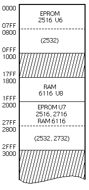
The memory map is decoded into 16 blocks of 4 kB. The first block is occupied by a 2 kB or a 4 kB EPROM. The second half of the second block is occupied by a 2 kB RAM chip. The third block is intended for the expansion socket, which can hold another 2 kB RAM or a 2 kB or 4 kB EPROM. All other blocks are not implemented on the main board.
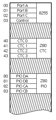
The I/O space is decoded into 4 blocks of 64 bytes each. The first block is assigned to the 8255, which is the system I/O device (keyboard, display and tape I/O). The second block is assigned to the Z80 CTC. The third block is assigned to the Z80 PIO. The fourth block is not assigned and can be used by expansion boards.
The Human Interface
A six digit 7-segment display and a 9 x 4 keyboard are used as main human interface to the MPF-1. A 8255 is used to control the display and keyboard, among a few other things. Normally the 8255 is controlled by the internal monitor program, thus usually you don't have to drive the 8255 yourself.
Port A
Port A of the 8255 is an input port.
- Bit b7 is the tape input bit.
- Bit b6 is connected to the "USER KEY", which is active low.
- Bits b5 - b0 are connected to 6 scan rows of the keyboard matrix. The input becomes low only when keys in the active column are pressed.
Port B
Port B of the 8255 is an output port.
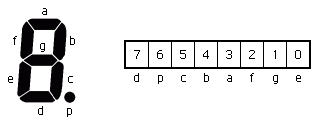
This port controls the seven segments and the decimal point of the display.
All output bits are active high.
The relationship between the segments and the bits of Port B can be seen in the diagram below.
Port C
Port C of the 8255 is also an output port.
- Bit b7 is the tape output bit. It is also connected to the speaker and the LED TONE-OUT.
- Bit b6 is used for monitor break control. Do not change this bit because it will crash the software.
- Bits b5 - b0 select one of the 6 displays and are connected to the keyboard matrix. Bit b0 is the rightmost display, while bit b5 is the leftmost display. All these bits are active high.
The Breakout Connectors
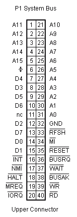
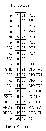
Please note that neither connector has a VCC pin. This means that any expansion module should have its own power supply. If you take a look at the 5 Volt regulator on the MPF-1 this is hardly a surprise. Considering the dimensions of the on board power supply you can't expect it to supply more than it already does (±0.5 A).
The Main Monitor Routines
The original user's manual mentions only a handful of monitor routines which can be used by user programs. This doesn't mean that you can't find any other useful routines in the monitor listing, but I would discourage you to use those as there is no guarantee that they exist in all monitor versions.
| Address> | Label | Function |
| 0624H | SCAN1 | Scan keyboard and display one cycle. |
| 05FEH | SCAN | Scan keyboard and display until a new key-in. |
| 0689H | HEX7 | Convert a hexadecimal digit to 7 segment format. |
| 0678H | HEX7SG | Convert two hexadecimal digits to 7 segment format. |
| 05F6H | RAMCHK | Check if the given address is RAM. |
| 05E4H | TONE | Generate sound. |
| 05DEH | TONE1K | Generate sound at 1 kHz. |
| 05E2H | TONE2K | Generate sound at 2 kHz. |
SCAN1
| Address: | 0624H |
| Function: | Scan keyboard and display 1 cycle from right to left. Execution time is about 10ms (9.97ms exactly). |
| Input: | IX points to the display buffer. |
| Output: | - If no key-down, then carry =1. - If key-down, carry flag =0 and A holds the position code. |
| Register: | Destroys AF, AF', BC' and DE'. |
| Description: | A 6 byte long buffer holds the segment patterns of the 6 displays.
The lowest byte of this buffer holds the right most display's pattern.
Register IX should point to the lowest byte of the display buffer before calling the routine.
If the Carry is 0 after this routine a key is down and its position code is in A. This means that this routine will return with the Carry is 0 for as long as the key is down. It's up to the programmer to accept the key only once, or repeat the key for as long as it is down. Please note that these are different values than the ones returned by the SCAN routine! |
SCAN
| Address: | 05FEH |
| Function: | Scan keyboard and display until a new key is pressed. |
| Input: | IX points to the display buffer. |
| Output: | A holds the internal code of the key pressed. |
| Register: | Destroys AF, B, AF', BC' and DE'. |
| Description: | A 6 byte long buffer holds the segment patterns of the 6 displays.
The lowest byte of this buffer holds the right most display's pattern.
Register IX should point to the lowest byte of the display buffer before calling the routine.
This routine returns the internal code of the key pressed. Please note that these are different values than the ones returned by the SCAN1 routine! |
HEX7
| Address: | 0689H |
| Function: | Convert a hexadecimal number into its 7-segment pattern. |
| Input: | The 4 least significant bits of A holds the hexadecimal value 0 - F. |
| Output: | A will hold the converted LED pattern. |
| Register: | Destroys AF only. |
HEX7SG
| Address: | 0678H |
| Function: | Converts two hexadecimal digits into the appropriate 7-segment patterns. |
| Input: | The 4 least significant bits of A holds the least significant nibble. The 4 most significant bits of A holds the most significant nibble. |
| Register: | Destroys AF, increments HL by 2. |
| Output: | The pattern of the least significant nibble is stored in (HL), which means the address pointed to by HL. The pattern of the most significant nibble is stored in (HL+1). HL is incremented by 2 by this routine. |
RAMCHK
| Address: | 05F6H |
| Function: | Check if the given address is in RAM. |
| Input: | HL holds the address to check. |
| Output: | Zero flag =1 if address is in RAM. |
| Register: | Destroys AF. |
TONE
| Address: | 05E4H |
| Function: | Generate sound. |
| Register: | Destroys AF, B, DE, HL. |
| Input: | C controls the frequency of the sound.
The period is about (44 + C x 13) x 1.12 µs.
The frequency is 200 / (10 + 3 x C) Hz.
HL contains the number of cycles. Maximum value is 34768. |
TONE1K
| Address: | 05DEH |
| Function: | Generate sound of 1 kHz. |
| Input: | HL contains the number of cycles. Maximum value is 34768. |
| Register: | Destroys AF, BC, DE, HL. |
TONE2K
| Address: | 05E2H |
| Function: | Generate sound of 2 kHz. |
| Input: | HL contains the number of cycles. Maximum value is 34768. |
| Register: | Destroys AF, BC, DE, HL. |
Keyboard Scan Codes
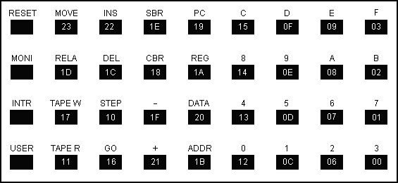
Position Key Codes as returned by the SCAN1 monitor routine.
Internal Key Codes as returned by the SCAN monitor routine.
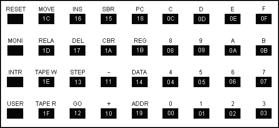
Why Multitech used different scan codes for these two routines beats me. But it is a fact and we simply have live with it.
Tip: You can always call the monitor routine KEYMAP (061DH) after calling SCAN1 to translate the position key code to an internal key code. This is not an officially documented monitor entry point though, which means that it may not work on all monitor versions.
Please note that the left column of the keyboard is not implemented in the keyboard matrix.
That's because RESET, MONI and INTR are Reset/Interrupt keys, and the USER key is directly connected to bit b6 of port A of the 8255.
This automatically means that you can not use the RESET, MONI and INTR keys in a user program (at least not easily).
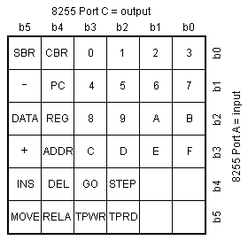
The keyboard scan codes and internal codes are quite fun, but I can imagine at least one occasion where they're of not much use to us.
Both scan routines don't allow you to press more than one key at a time.
Thus if you want to allow a user to press more than one key at a time you'll have to scan the keyboard yourself.
The little table on the left shows you exactly how the keys are connected to the scan matrix.
Again you won't find the 4 keys on the left keyboard column in the table.
I had to write a little program to find out how the keys were connected to the scan matrix. This program will be available in the experiments corner.
Special RAM Locations
Below is a small table with the most important RAM locations which can be found on the standard MPF-1, which means an MPF-1 with 2 kB of RAM memory.
| Address | Function |
| 1800H - 1D00H | User program and data memory. The user's program may be bigger than this, but the INS and DEL keys work only in this range. |
| ???? - 1F9EH | Default user stack area. User may place the stack at any free location if necessary. Please keep in mind that the monitor stores all internal register in the user stack during debugging and when the user's program returns control back to the monitor. |
| 1F9EH - 1FAEH | System stack area. Do not alter this area! Used by the monitor program. |
| 1FAFH - 1FFFH | Monitor scratch pad area. Be careful when changing anything in this area. It might upset the monitor program. |
| 1FF0H | Key presses beep only if this value is 55H |
| 1FF5H | Used to distinguish between a warm reset (value A5H) and a cold reset (any other value). |
| 1FFEH - 1FFFH | User's IRQ Mode 1 vector. Points per default to 0066H. May be changed by user program to handle IRQ's in Mode 1 on its own. |
Reset Sequences
There are 2 ways to reset the MPF-1:
Cold Reset (power up Reset):
- Disable interrupt (IFF set to 0).
- I register is set to 00H.
- Interrupt mode is set to 0.
- User's PC is set to 1800H.
- User's SP is set to 1F9FH.
- Break point is disabled.
- Contents of 01FEEH is set to 066H and 01FEFH is set to 000H. When code beginning at 00038H is executed the CPU will jump to 00066H. This is equivalent to pressing the MONI key.
- MPF-1 is displayed one character at a time from right to left.
Warm Reset (RESET key pressed):
- Disable interrupt (IFF set to 0).
- I register is set to 00H.
- Interrupt mode is set to 0.
- User's PC is set to 1800H.
- User's SP is set to 1F9FH.
- MPF-1 is displayed immediately.
Please note that a warm reset does not destroy the user's program.
RAM address 1FE5H distinguishes between a warm Reset (holds A5H), or a cold reset (holds any other value).
