Sonoff - Cheap Remote Controlled Mains Switches
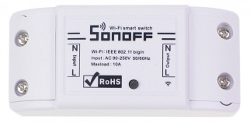 I'm running some 10 Sonoffs with Tasmota for more than 3 years now and I have ordered a few more to control some of our shutters.
Shortly after moving into our new house, almost 4 years ago now, I installed most of them.
Tasmota is really great software.
I never had any issues with it.
I would still be running my first version V6.6.0 if it had featured TLS encryption for MQTT out of the box back then.
Three years ago I used the quick and dirty way to install a stock version of Tasmota because I had only little time to spend on my hobbies.
The only problem with the stock version is that the MQTT messages are not encrypted.
I compensated for the lack of encryption by firewalling my unencrypted MQTT server to my public IP address at home.
It kept my MQTT setup secure, but it was not an ideal setup.
Now I have been able compile a custom version of Tasmota with TLS enabled.
Thus it's time to update this page to include this upgrade.
This page is not one of my projects as such, all the credit should go to Itead, for creating such a nice small and affordable mains switching device and to Theo Arends, who has written a wonderful alternative firmware for these devices.
This page is merely a collection of the steps required to flash new firmware and deploy the Sonoffs plus a brief description on how to use them.
That way I can easily repeat these steps should I need more Sonoff devices at a later date.
I won't go explaining how to setup your own MQTT broker or how to secure it.
You could use a public MQTT broker in case you don't want to setup one yourself.
I'm using Mosquitto as an MQTT broker myself.
It's easy to set up and has worked perfectly for me so far.
I highly recommend it, but it is by no means the only option out there.
Original Software
The Sonoff switches come with eWeLink firmware, which connects your Sonoff to their server.
The advantage of that is that you only have to install the EWeLink App on your phone and you're good to go.
You can control all your Sonoffs from all over the world using this app.
However I would rather like to run it all from my own server.
It is a bit more work to set it all up, but it ensures me that it will keep working for as long as I keep my server running.
I won't have to worry about their server to be decommissioned at some point in the future.
And I'm not interested in controlling my Sonoffs with an App anyway.
I'd like my server to control them, at least most of the time.
At first I did manage to find a website explaining how to use your own MQTT broker with the original Sonoff firmware.
Later I've learned that Tasmota is a much more sophisticated alternative to the original firmware.
It would break the warranty of course, but who cares, for a device with the price tag of about 5 Euros, delivered.
Tasmota it is going to be.
A big thank you to Theo Arends for making this program publicly available.
Which Way To Go?
I've tried different flashing methods before I finally settled on the one which works best for me.
First I tried the Over The Air method because that doesn't require any additional hardware. Sadly it appeared that not all versions of the Sonoff firmware agree to that method any more.
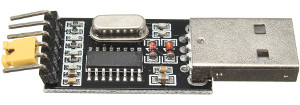 Then I tried to use an off the shelf USB UART board from Banggood.
That failed because the serial chip on that adapter could only supply 50mA to the Sonoff, whereas the Sonoff needs at least some 80mA during flashing.
Therefore the supply voltage dropped to about 3V.
I didn't even bother to try to flash Tasmota in the Sonoff with this setup because the Sonoff might switch off half way during the flashing process, which is probably not such a good idea.
Then I realised that the Raspberry Pi has all the features I need, it has a 3.3V voltage regulator and a serial port built in. That would be ideal. But alas, the Raspberry Pi reboots or simply hangs when I connect its 3.3V to the Sonoff. Thus this method theoretically could work after power cycling the Raspberry Pi. However I don't find that an ideal solution either.
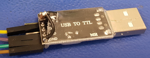
Finally I decided on using the off the shelf USB UART anyway, with a slight modification. I've added a 3.3V regulator to it (LP2950-33), which can supply some 100mA.
I could have gone for an external power supply for either the Raspberry Pi or the USB UART option, but that was too easy. I mean that's easier said than done while my hobby room was still under construction. I could dig up a power supply, but where are my test leads and alligator clips…..?
A little side note. After I've installed LinuxMint 21 on my computer it appeared that the driver for my CH340 USB to Serial chip was no longer included in the installation. Other distributions may be affected too. The lsusb command showed that the chip was recognised correctly, as you can see in the output below.
Bus 002 Device 009: ID 1a86:7523 QinHeng Electronics CH340 serial converter
However, there was no /dev/ttyUSB0 device. This meant that I could not continue until I could solve that problem.
A quick search on the internet taught me how to get control back over my USB to serial converter. Sparkfun explains how you can add the driver for the CH340 chip.
After installing the driver my USB to serial interface was still not recognized. It appeared that the brltty driver claimed the device as soon as it was recognized. Fortunately I'm not blind, so I have no use for the Brail TTY, away it goes.
sudo apt purge brltty
After that my programming device was working again. And as a bonus my Arduino Nano, which also uses a CH230 chip, could again be programmed by my computer.
Getting The Software
You can download a ready built binary file from Github. Usually you would need the tasmota.bin for the Sonoff Basic version. You can also select one of the non English versions if English is not your thing.
Unfortunately one version you can't select is a version with TLS encryption for MQTT.
Until now you had to compile that version yourself, from the provided source code.
That was one step too far for me, some 3 years ago.
Now I finally had some time to figure out how to compile my own version.
In my case it is the stock Tasmota version with TLS for MQTT enabled.
Compiling your own version is a very easy nowadays.
However you're welcome to download my compilation of version 12.3.1.5 directly from my website.
That saves you the trouble of compiling it yourself.
The only downside is that I won't keep updating the firmware with newer versions if I don't feel the need to do so.
So you're stuck with this version, for the time being.
Installing Programming Tools
These tools are only required to flash an existing Tasmota firmware into your Sonoff device.
It's got nothing to do with compiling your own versions, yet.
I can only show you how to flash the Sonoff with Tasmota firmware using Linux.
This works equally well on a desktop computer as on a Raspberry Pi.
You could also use a Windows machine if you don't have access to a Linux computer, but I have no experience on that.
Before you can start flashing you need a few things, apart from a UART with 3V3 signal levels and 4 Dupont jumper wires.
- First you'll need Python3. But that is pretty much installed per default on most Linux machines these days.
- Second you'll need to install the python3-pip package manager.
- Third you'll need to install the esptool.py software.
Here's how to install all of these on a Debian based machine:
sudo apt install python3 python3-pip
sudo pip install esptool
If you add yourself to the dialout group you can flash your Sonoffs without having to become root. Otherwise you'll have to place the sudo command in front of the flash command later on.
sudo usermod -aG dialout <username>
You'll have to logout and login to your terminal again to activate this last setting.
Connecting The Programmer To The Sonoff
Important note! Make sure the Sonoff is disconnected from the mains before the cover is removed! Mains voltages are dangerous! You don't need the mains connection during flashing.
Opening the Sonoff is quite easy. Simply remove both protective caps over the input and output wires and pull the bottom plate from the Sonoff away from the top shell, using your finger nails or a flat screwdriver.

Locate the programming port, which consists of 4 or 5 holes in a row. The number of holes depends on the model of your Sonoff device. The holes may or may not be labelled. Below is a picture which designates the hole numbers, in case yours are not labelled.

In any case 4 holes are needed for flashing, which are 3V3, RX, TX, and GND respectively. The 3V3 hole can be identified by its square solder pad. A possible fifth hole will probably be labelled GPIO14 and is not required for flashing.
Some people choose to solder a header into these holes, on which it will be easy to connect 4 jumper wires. I personally don't like this very much, especially with the newer revisions of the Sonoff Basic. The circuit board is a bit crowded around the programming holes and reaching them can be a bit difficult.
 It is way easier to use the bottom side of the PCB for the programming header.
But soldering it there is a problem, for the PCB wouldn't fit into the housing after doing so.
Therefore I have bent each short end of the header pins outward, just a little bit. Every other pin is bent to the opposite direction, sideways. That way the header simply plugs into the holes and makes fairly good contact, even without soldering. The contacts have to last for only a few minutes. After flashing the header can simply be removed again.
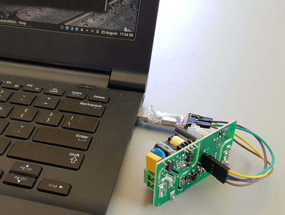
Once the header is inserted into the holes of the Sonoff you can already make 3 of the 4 connections using Dupont jumper wires. Connect the pins labelled GND on both ends with one jumper wire. Connect the TX line on the Sonoff side to RX on the serial adapter side. Connect the RX line of the Sonoff side to the TX pin on the serial adapter side.
Now press and hold the button on the Sonoff while connecting the 3V3 line of the Sonoff to a 3V3 power source, which can supply at least some 100mA. This will put the Sonoff in bootloader mode, where it will wait for the new application software to arrive. The LED does not light up in this mode. Once the Sonoff is powered up you can release the button.
Flashing Tasmota
Now open a terminal on your computer and cd to the directory which holds the tasmota.bin or my tasmota-tls.bin version of the file. Then enter the following commands (you might have to place sudo in front of the command):
esptool.py -p /dev/ttyUSB0 erase_flash
esptool.py -p /dev/ttyUSB0 write_flash 0x000000 tasmota-tls.bin
On a Raspberry Pi you should replace ttyUSB0 by ttyAMA0. And when you have pressed enter you will see the following appear on the screen:
esptool.py -p /dev/ttyUSB0 erase_flash
esptool.py v4.4
Serial port /dev/ttyUSB0
Connecting....
Detecting chip type... Unsupported detection protocol, switching and trying again...
Connecting...
Detecting chip type... ESP8266
Chip is ESP8266EX
Features: WiFi
Crystal is 26MHz
MAC: ec:fa:bc:15:24:a2
Uploading stub...
Running stub...
Stub running...
Erasing flash (this may take a while)...
Chip erase completed successfully in 2.6s
Hard resetting via RTS pin...
esptool.py -p /dev/ttyUSB0 write_flash 0x000000 tasmota-tls.bin
esptool.py v4.4
Serial port /dev/ttyUSB0
Connecting...
Detecting chip type... Unsupported detection protocol, switching and trying again...
Connecting...
Detecting chip type... ESP8266
Chip is ESP8266EX
Features: WiFi
Crystal is 26MHz
MAC: ec:fa:bc:15:24:a2
Stub is already running. No upload is necessary.
Configuring flash size...
Flash will be erased from 0x00000000 to 0x000abfff...
Compressed 704192 bytes to 503922...
Wrote 704192 bytes (503922 compressed) at 0x00000000 in 44.5 seconds (effective 126.6 kbit/s)...
Hash of data verified.

Leaving...
Hard resetting via RTS pin...
I have included the first command to erase the old version from the chip after finding out that stored settings from a previous version can lead to conflicts with the new version.
Better be safe than sorry.
The programming process takes less than a minute.
After that you may have to restart your Sonoff by briefly removing the 3V3.
Then the LED on the Sonoff should start to blink.
Now we don't need to be inside the Sonoff any more. You must disconnect the programming header from the Sonoff and close it again before you should plug it into the mains.
And Now We're Going To Enable TLS For MQTT
It works, in my case for more than 3 years up until now.
However I really wanted to enable TLS.
Nowadays it is fairly simple to compile your own version of Tasmota thanks to Docker-Tasmota.
The TLS version is slightly bigger than the stock version of Tasmota.
This means that Over the Air software updates won't work any more.
I've been running version 6.6.0 of Tasmota for over 3 years without ever having the need to update the software.
Therefore the fact that FOTA doesn't work any more is not a big deal for me.
I could disable some features which I don't need to free up some memory, but I couldn't be bothered to do so.
Here are all the steps required to setup a working environment on a Linux computer these days. It can even be installed on a Raspberry Pi. Compiling the software on a Raspberry Pi will take a bit longer than on a normal computer though.
Before you start, you'll need docker and git. If you don't have these installed already, all you need to do is:
sudo apt install git docker
It is a good idea to add the docker group to your user. That way you can run docker commands without having to become root.
sudo usermod -aG docker <username>
After that you'll have to log out and log back in to your terminal in order to make the user change effective.
Create a new directory somewhere in your home directory. I normally use a directory named src for this purpose. Then cd into this directory and then enter the following command:
git clone https://github.com/tasmota/docker-tasmota.git
This will install everything you need, super simple. After installation, simply cd into the new directory and start the complie.sh script:
cd docker-tasmota
./compile.sh
The first time you run this command it will download the latest Tasmota source code from git and will compile it as it is. It may take a few minutes to complete, especially when you're running it on a Raspberry Pi. But eventually the prompt should return. Then use the nano user_config_override.h command and add the following lines at the end of this file.
#ifndef USE_MQTT_TLS
#define USE_MQTT_TLS
#define MQTT_TLS_ENABLED       true
#endif

#define MQTT_PORT              8883
Then start the compilation again by entering the following command again:
./compile.sh
Once the compilation is complete a new version of tasmota.bin can be found in the directory Tasmota/build_output/firmware, which is some 600 bytes larger than the original version.
With this new version TLS for MQTT is enabled.
Please note that the encryption is only added to MQTT, not to the web interface of the Tasmota, that will remain plain HTML.
Connecting To Your Sonoff
Now it's time to connect your Tasmota device to your Wifi network.
Conveniently a new Sonoff device acts like an Access Point.
You'll need a Wifi enabled computer, phone or tablet to connect to this Access Point.
This Access Point will look like sonoff-xxxxxx-yyyy, where xxxxxx is a random 6 digit hexadecimal number and yyyy is a random 4 digit number.
Connect your Wifi enabled device to this access point.
There is no security required here.
Once your device is connected open a browser and go to address http://192.168.4.1.
This will open the setup page for your Tasmota Sonoff.
![]()
Simply click on your network and it will be copied into the WiFi Nework box.
You can also enter the network manually.
Or, if there are too many networks, you may have to click Scan for all WiFi Networks to show them all.
Then also enter the WPA2 code for that network in the WiFi Password box.
And finally click Save.
Now some very clever magic happens.
Your WiFi credentials are stored into the Sonoff's memory and the device reboots.
It then connects to your home network.
But still it is able to report the IP address it received from your network to the page you're looking at.
Now enter that URL into the address bar of your browser and you'll be presented with the main Tasmota page.
Later you can switch to Access point mode again by shortly pressing the Sonoff button 4 times in quick succession.
Configuring Your Sonoff
Point your browser to the IP address of your Sonoff. It will present you with a page containing some buttons with which you can control and configure your Sonoff.
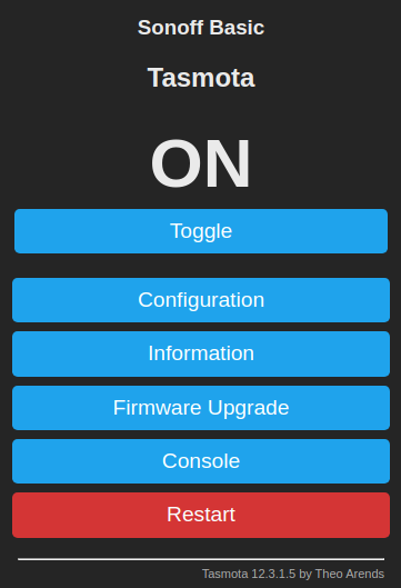
The Toggle button is the first one you probably want to play with.
It toggles the output between on and off.
Nice to confirm that all your hard work so far hasn't been in vain.
But the real fun begins when you press the Config button.
It will bring up a menu with the most interesting settings.
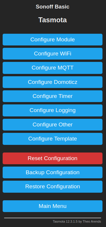
We have already seen the Wifi Setup menu. For me the most interesting one is the Configure MQTT button. The other configuration menus don't apply to my MQTT setup, so I'm going to skip them here and leave them for you to explore.
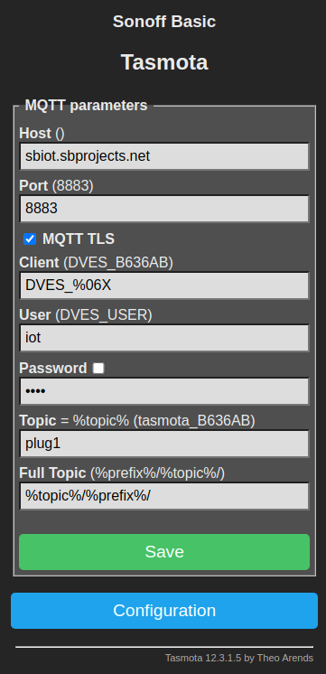
The first two fields apply to your MQTT broker.
Simply add the URL of your broker and the port number.
Usually this port number would be 1883 for unencrypted traffic, but since we're going to use encrypted traffic we need to enter 8883 here and tick the MQTT TLS box.
The Client field can be left as is.
But the User and Password fields need to reflect the login credentials of your MQTT broker.
You can name the topic the way you like.
In this example I have named it plug1, which implies that I have more than one.
I have also changed the full topic field.
Originally Tasmota uses a topic like command/device, whereas I prefer the order device/command.
Simply press Save when all the fields are entered and your Sonoff is ready to be controlled by your MQTT broker.
MQTT
And now for the moment we've all been waiting for, controlling your Sonoff using MQTT. For that to work we need an MQTT client on our computer. Again mosquitto is the one I use as a command line interface MQTT client. To make life easier I've added two aliases in my .bash_aliases file, like below:
alias iot_sub='mosquitto_sub -h mymqttbroker.net $(cat ~/.mqttpwd) -p 8883 --capath /etc/ssl/certs/'
alias iot_pub='mosquitto_pub -h mymqttbroker.net $(cat ~/.mqttpwd) -p 8883 --capath /etc/ssl/certs/'
That will save me a lot of typing quite mysterious looking magic spells for each command I want to give. If your MQTT doesn't use encryption you can skip the --capath bit. I've also created a file named .mqttpwd in my home directory containing only one line with my broker's user name and password:
-u username -P password
And if you chmod that file as 600, no one else can read your password.
With these preparations done giving manual MQTT commands has become a whole lot simpler. Let's open a terminal and enter the following command:
iot_sub -t sonoff/stat/#
Or in my example, where I've renamed the Sonoff device to plug1 it would be:
iot_sub -t plug1/stat/#
That terminal will now continuously update you on the output state of the Sonoff switch, no matter how it was switched.
{"POWER":"ON"}
ON
Open a second terminal and give one of the following commands:
iot_pub -t plug1/cmnd/Power -m 0
iot_pub -t plug1/cmnd/Power -m 1
iot_pub -t plug1/cmnd/Power -m 2
The first command will switch you Sonoff off. The second one will switch it on. And the third command toggles the state of your Sonoff switch.
Now you know the basics on how to control your Sonoff.
Other Settings
Not all configurations can be made from the web interface, probably due to memory constraints in the Sonoff devices.
You can access the command line interface from the web interface by clicking the Console button in the Main menu where you can see status updates from the device and enter commands.
A list of all the available commands can be found on the Sonoff Wiki page.
It is also possible to configure these same settings through MQTT, so you might consider automating these configuration settings from a central computer.
Here are a few settings you might want to change:
Automate the timezone:
These settings are only useful if you intend to use the built-in timer of your Sonoff device. When you're only interested in MQTT control, these settings can be left as they are.
Per default the timezone is set to a fixed offset from UTC. I prefer automatic switching between daylight saving times. For that you'll have to set the Timezone to 99.
timezone 99
The default daylight saving rules work for me. It is set to the European rules anyway.
Your location:
Per default my Sonoff was placed on top of the Eiffel tower in Paris. This only affects the sunrise/sunset times. So if you want those to be correct you should set the Longitude and Latitude values to your own location.
latitude 51.604112
longitude 5.161626
The commands shown above are by far not the only commands you can give your Sonoff device. More can be found on the Sonoff Wiki pages.
You can also configure the time zone and your exact location by using the MQTT commands below:
iot_pub -t cmnd/sonoff/Latitude -m "51.604112"
iot_pub -t cmnd/sonoff/Longitude -m "5.161626"
iot_pub -t cmnd/sonoff/Timezone -m "99"
Or you could check their settings by publishing the same command, with an empty message. Don't forget to have a terminal open where you subscribe to the status of you Sonoff, otherwise you won't see anything.
iot_pub -t cmnd/sonoff/Latitude -m ""
iot_pub -t cmnd/sonoff/Longitude -m ""
iot_pub -t cmnd/sonoff/Timezone -m ""
