SB-Bus Drivers Introduction

Just in case you didn't know by now, the SB-Bus enables you to connect up to 125 different SB-Bus devices to one standard serial port on any type of computer.
In fact the SB-Bus is nothing more than a special protocol (a set of rules) and a certain way to distribute the electrical signals.
The SB-Bus protocol is described on the SB-Bus pages on this site.
Those pages also describe the required electrical signal properties.
You need some kind of adapter to change the computer's COM port RS-232 signals into SB-Bus signals and back.
This page describes a few different ways to implement such an adapter.
It's up to you to decide which one you are going to build, depending on your needs.
The Passive SB-Bus Cable (shown on the left) is especially suitable in case you're only interested in connecting just one SB-Bus device.
It can simply be used to connect one SB-Bus device directly to a computer's COM port.
It can also be used if you want to take one of your SB-Bus devices on a little field trip.
If you want to connect more than 1 SB-Bus device to the COM port you'll have to make an Active adapter.
You can use the Active SB-Bus cable (shown on the right) if you want to connect up to 10 SB-Bus devices to one standard serial port.
In case this is still not enough for you, you can decide for an adapter that can drive up to 40, or even 80 SB-Bus devices.
It is also quite simple to extend this idea to create an adapter that is capable of driving the absolute maximum number of 125 SB-Bus devices.
Passive SB-Bus Cable
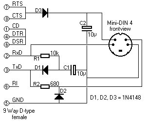 The main advantage of the passive SB-Bus Cable is that it doesn't require an external power source.
All necessary power is "borrowed" from the RS-232 signals found on the PC's COM port.
Due to this limited power the passive SB-Bus Cable has very little drive capacity.
It can drive only one SB-Bus device, maybe two if you're extremely lucky.
Two voltages are derived from the PC's COM port.
Under normal circumstances the DTR line is at about +10V.
This voltage is connected to the + side of C2 by D3.
When no data is sent by the computer, the voltage on the TxD line is about -10V.
Diode D1 charges C1 with this negative voltage, so that it can still be available during data transmissions.
Resistor R1 pulls the RxD line to -10V. The connected SB-Bus device has a transistor which can connect the +10V to the RxD pin. This transistor is part of the output opto-coupler.
The TxD line can drive the LED in the SB-Bus device's receive opto-coupler through the series resistor R2. Diode D2 limits negative voltages applied to the opto-coupler's LED to about -0.6V.
 The diagram shows how the signals are connected to the Mini-DIN male plug, as seen looking into this plug.
In the SB-Bus device the 2 pins on the left are connected to the send opto-coupler's transistor, while the 2 pins on the right are connected to the receive opto-coupler's LED.
Please note that this interface doesn't allow a common wire coming from the send/receive opto-couplers in the SB-Bus device. The send LED and the receive transistor should remain completely isolated from each other!
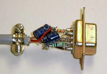
There are many ways in which you can create a simple project like this.
The picture to the right shows how I've built mine, in the old fashioned 3D-technique!
Everything fits nicely in the cap of the 9-way D-type connector if you use small components.
Especially the capacitors should be chosen as small as possible.
In my case the connector cap is covered with a conductive coating.
Therefore I had to wrap the circuit in some insulating tape before closing the caps.
Active SB-Bus Cable
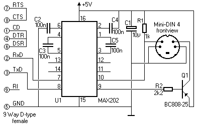 As opposed to the passive SB-Bus Cable, the active SB-Bus Cable does need an external power source.
Due to this power it has more drive capacity, and can drive about 10 SB-Bus devices.
The exact maximum number of SB-Bus devices that can be driven also depends on the total cable length.
There are many ways to get this power. One way is to "borrow" it from the keyboard connector, like I do (see the title picture). An other way is to build the whole interface in an AC power adapter. Surely there are many more power sources that can be used, but in any case see to it that it delivers a regulated +5V and that it can supply at least 100mA.
I used a MAX202 to convert the RS-232 signal level to TTL level and back.
Of course other ICs with similar functions can be used here.
The 4 capacitors around this IC have the traditional function of doubling and inverting the +5V to create +10V and -10V.
The transistor of the SB-Bus device's transmit opto-coupler can short input pin 10 to ground.
That signal is then transferred to the RS-232 side of the IC.
All transmit transistors of all connected SB-Bus devices are connected in parallel forming a wired-AND system.
The LEDs of the SB-Bus device's receive opto-coupler is driven by the PNP transistor Q1.
Any suitable type of PNP transistor can be used here, as long as it can drive up to 100mA.
I selected the BC808-25 in this design because it's an SMD type.
The diagram shows how the signals are connected to the Mini-DIN male plug, as seen looking into this plug. In the SB-Bus device the 2 pins on the left are connected to the send opto-coupler's transistor, while the 2 pins on the right are connected to the receive opto-coupler's LED.
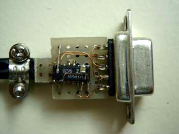 Again there are many different ways to build this project.
I've built mine in the cap of a 9-way D-type connector.
It goes without saying that it is inevitable to use SMD type components to fit a circuit like this in such a tiny space.
I can imagine that building it like this might cause you some problems.
In that case you can always build the circuit with normal through-hole components.
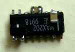 First I started by modeling the ceramic SMD capacitors, the 2 resistors and the transistor around the SMD IC in 3D-technique.
Then I mounted the whole circuit to a tiny piece of pad board, fixing it with some "thick" wires.
All other wires are made of thin insulated copper wire.
C1 is mounted under the piece of pad board, and its wires are used to fix the IC to its shown position.
I used a feed-through type of keyboard connector to "borrow" +5V from the PC's keyboard connection.
The keyboard can still be connected to the back of this feed-through connector.
If can't get such a connector yourself you may also consider getting the power from a free USB port on your PC.
Even More Drive!
The Active cable has only one port, which can drive a maximum of about 10 SB-Bus devices.
Driving more devices is not simply a matter of increasing the drive power of Q1.
Adding more devices automatically means an increase of the total cable length, and thus an increase of cable capacitance.
The best way to increase the maximum drive capacity is to add more, separate connection sockets, each powered by its own driver transistor.
This will also reduce the maximum current in case of a short circuit of the output signal too.
If you intend to add more ports, you should also add more inputs to the MAX202.
All these inputs should be combined by some kind of AND gate.
Preferably all the inputs should contain a Schmitt-Trigger circuit.
One could use a 74LS13, a dual 4 input Schmitt-Trigger NAND, followed by the second NAND switched as inverter to create a 4 input Schmitt-Trigger AND gate.
That would increase the maximum number of SB-Bus devices that can be serviced to about 40 already.
Another approach could be to use a 74LS541 Octal Schmitt-Trigger buffer, followed by a 74LS30, an 8-input NAND gate whose output should be inverted again to obtain an 8 input Schmitt-Trigger AND gate.
The output of such a composed AND gate should be connected to pin 10 of the MAX202.
In any case all Schmitt-Trigger inputs should contain a 1k pull-up resistor to +5V to ensure proper logic levels and short rise times.
As long as all the inputs are held high, the output will remain high.
However as soon as at least one input is taken low by one of the Slaves, the output will go low too (AND function).
