Raspberry Pi EPROM Emulator
My love for assembly language programming dates back to my first programming steps on my first real computer, my Apple ][, somewhere in 1983.
Even today I prefer programming in assembly language above any other programming language, no matter how tempting it is to quickly program an application in Python on a Raspberry Pi.
The last decade or so I’ve been spoiled by the ease in which microcontrollers like the AVR can be turned into a project in a matter of hours.
Hook them up to a power source, connect the input and output lines, program it using an In Circuit Programming tool and the job is as good as finished.
However, despite of all that luxury I still love to do it all the old fashioned way occasionally.
And with the proper tools this is not too difficult to achieve.
Program Development, The Old Fashioned Way
In the old days you’d have to connect RAM, EPROM, Timers, I/O peripherals and UARTs to the microprocessor’s address and data busses.
It took days to wire them all up, just to get to the point where you would start when using a modern microcontroller.
In the beginning I used a whole lot of EPROM chips to write and test my program in progress with.
After writing the next version of the program I had to burn the code into an EPROM, remove the old one from its socket in the target system and then put the new one in.
Every time I had 4 used EPROMs I could place them under the UV eraser again, so they could be reused again about half an hour later.
What Is An EPROM Emulator?
Simply put it is a device which, to the target system, behaves like an ordinary EPROM or ROM.
A target system doesn’t usually see the difference between an EPROM or ROM, because both EPROMs and ROMs are programmed outside the target system.
An EPROM emulator consists of some amount of RAM, which is connected to the target system.
The target system can only read from that RAM for the lack of a write enable line to the RAM.
The RAM is written with the latest version of your program by a separate system, during which the target system is best held in reset to prevent it from crashing.
Once your program is finished it can be burned into a normal EPROM which then replaces the EPROM Emulator on the target system.
So basically an EPROM emulator is an In Circuit Programming tool for microprocessor systems. An EPROM emulator is also called an EPROM simulator. I used the word simulator in the past, but I think emulator is more common these days. Call it whatever you like. It’s the same thing.
This Is Not My First EPROM Emulator
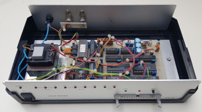
My first EPROM emulator was built around a Z8 processor and contained 64k of RAM to simulate up to 64k of EPROM.
The software and hardware were expandable to accommodate more RAM, but I never needed more.
The emulator was controlled over the SB-Bus of course.
This EPROM emulator still works today.
However I have never described it as a project.
I have to dig deep to find the circuit diagram of it.
And the code was written on an Apple ][, which I have salvaged from floppies in 2017.
And that’s just about all the documentation that exists around it.
Later I’ve built a slimmed down version, which could only emulate EPROMs of 32kB in size. It is also controlled over the SB-Bus. This one is fully documented elsewhere on my website.
Taking It To The 21st Century
At only 9600 baud the SB-Bus is tediously slow, compared to today’s standards.
It was OK when computers were all slow.
I guess we’re a bit spoiled nowadays.
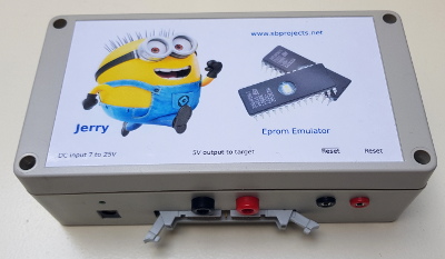
Anyway, why don’t I start a new project, using a Raspberry Pi Zero W to control the new EPROM emulator?
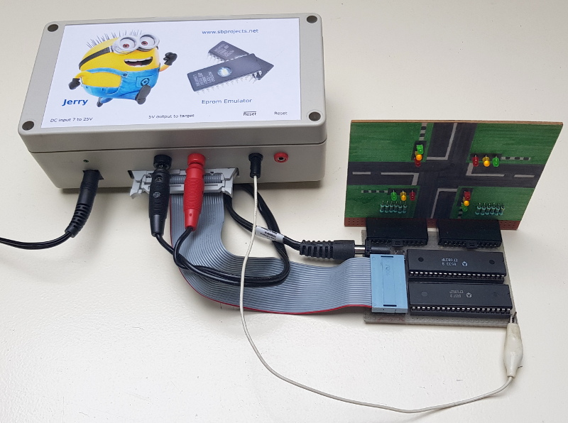
And here it is.
The result is just a box, which requires a power connection while its ribbon cable plugs into the EPROM socket of the target system.
And that’s it.
The software on the Raspberry Pi takes care of writing the ROM image to the emulator’s RAM, while holding the target system in reset.
You can even run the SB-Assembler on the EPROM emulator, avoiding the need to upload the ROM image to the EPROM emulator at each iteration.
That way it’s a complete self contained unit.
Features
This Eprom emulator can emulate EPROMs ranging from 2k Bytes up to 64k Bytes. Here’s a list of emulated devices:
| 2716 | 2k Bytes | (using a 24 pin adapter cable) |
| 2732 | 4k Bytes | (using a 24 pin adapter cable) |
| 2764 | 8k Bytes | (using a 28 pin adapter cable) |
| 27128 | 16k Bytes | (using a 28 pin adapter cable) |
| 27256 | 32k Bytes | (using a 28 pin adapter cable) |
| 27512 | 64k Bytes | (using a 28 pin adapter cable) |
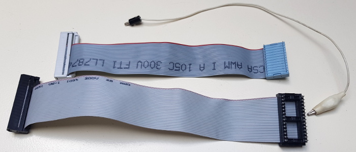
Two adapter cables exist, a 24 pin and a 28 pin version. These cables are directly pin compatible with the above mentioned 24 pin and 28 pin devices.
Technically speaking the EPROM emulator can also emulate some other devices, like the 2708 and the 2532, which have slightly different pinouts. However you’d need a special adapter cable to connect those. Be specifically careful with the 2708, because it carries 12V and -5V on some pins, which will very likely kill the EPROM emulator.
I have thought long and hard on the power supply features of the EPROM emulator.
Should I power the EPROM emulator from the target system?
Or should I make it possible to power the target system by the EPROM emulator?
Should this be done configurable through software, or by a manual switch?
Powering the EPROM emulator from the target system is not desirable, I think.
It is not that the EPROM emulator is very power hungry, at less than 200 mA.
It’s more the current spikes generated by the wifi module of the Raspberry Pi Zero W which worry me the most.
Therefore I’ve given the EPROM emulator its own power supply.
An internal switch mode regulator generates the required 5V, with lots of amps to spare for the target system.
This regulator allows a wide input voltage range.
It eats anything between 8V and 24V, or even more.
A separate 5V output can be connected to power the target system if you wish.
This way the target system can draw some 2A from the EPROM emulator without any problems.
This wouldn’t have been possible if I had decided to power the target system through the adapter cable, which can’t handle that much current.
Care should be taken not to overload the power output though, because that will very likely cause a reboot of the Raspberry Pi Zero W.
Two open-collector reset outputs are provided.
An active low reset and an active high reset.
Most processors need an active low reset signal.
The only processor family I know of that needs an active high reset is the 8051 family.
You can connect the appropriate reset output directly to the Reset input of your target processor, which usually is driven by a simple RC circuit.
Directly after booting the reset outputs are both activated.
The reset is only deactivated after a successful upload of your target file.
Everytime after that the reset outputs are activated during each successive upload.
If an upload fails the reset outputs remain activated.
Setting up the Raspberry Pi Zero W
Although the Eprom Emulator can run on just about any flavour of the Raspberry Pi family, and possibly many of its competitors, I limit the description to the Raspberry Pi Zero W now, because that’s what I’ve used in my project.
Please note that I’m very brief here, it’s beyond the scope of this page to teach you how to setup a Raspberry Pi in general.
As usual I start with writing my Nox image to a micro SD card.
This ensures me that the ssh server is active.
I also create the file /etc/wpa_supplicant/wpa_supplicant.conf on the SD card.
I simply mount the SD card on my Linux machine to do that.
Please search the internet to find a way to copy a file over to a Linux file system when you’re using Windows.
The above mentioned file contains something like:
network={
    ssid="mywifi"
    scan_ssid=0
    key_mgmt=WPA-PSK
    psk="myWPAkey"
    id_str="fromhome"
}

network={
    ssid="computerclubwifi"
    scan_ssid=0
    key_mgmt=WPA-PSK
    psk="clubsWPAkey"
    id_str="computerclub"
}
You can add as many networks you know to this file. The Raspberry Pi will then automatically log in to any of them whenever it is within its reach.
Then move the SD card over the Raspberry Pi, power it up and change your default password. Also consider copying your ssh public key over to the Raspberry Pi so you can login the its ssh server without having to enter a password in the future.
Then copy the Eprom Emulator software over to the Raspberry Pi. A good place to put them is the ~/src directory. Then create a symbolic link to the epromemulator.py program in the ~/bin directory. That allows the program to be started by the epsim command, without bothering about its path.
ln -s ~/src/epromemulator.py ~/bin/epsim
You can also add a line in your crontab, which will light the Power LED shortly after starting you Raspberry Pi. Later when you do a sudo shutdown the Power LED will switch off automatically, indicating it is safe to power down the Raspberry Pi. Execute the command crontab -e and add the following line at the end of the file:
@reboot /home/pi/src/powerled.py
Control of the Raspberry Pi Zero W
There are many ways to control the the Eprom Emulator.
I prefer to run it headless, which means that no keyboard or monitor are attached to it.
The machine is simply connected to my network over Wifi and I ssh into the machine to control it.
Small projects can simply be assembled on the Pi Zero W using my SB-Assembler.
And since version 3.03.00 of the assembler you can use the .RU directive to run the EPROM emulator software after each successful assembly, automating the upload of the brand spanking new version of your application to the target system.
For larger projects the Pi Zero W may be a bit on the slow side.
It will still work, but it may become a bit annoyingly slow.
Then it might be better to use a more powerful computer to do the editing and assembling, after which the target file can be copied over to the Pi, which then in turn can upload the file to the target system again.
You can also share the main computer’s disk with the Pi, or the other way around to skip the file copying task.
It is beyond the scope of this article to explain how to share files on a Linux system.
Nautilus (on Ubuntu) or Nemo (on Linuxmint) can do that out of the box.
Other file managers may need the help of a tool call gigolo.
And if you want to do everything on the command line you could have a search for sshfs on Google.
Software
I’ve written the control software in Python3. Not the fasted language, but fast enough for this purpose. Maybe, in the future, I might get tempted to rewrite the program in C or other compiled language in order to increase the upload speed. Don’t hold your breath until I do though.
The software requires Python3 and the Python3 GPIO module, which can be installed by executing the command:
sudo apt install python-pip python3-pip
sudo pip3 install --upgrade pip3
sudo pip3 install RPi.GPIO
I usually make a symbolic link to the EPROM emulator program in my ~/bin directory like this:
ln -s ~/src/epromemulator/epromemulator.py ~/bin/epsim
After which the program can simply be started by giving the epsim command. The command takes the following parameters:
-a |
This parameter is optional. Animated programming. A dot is shown for each 256 bytes written. |
-f |
This parameter is optional. Follow the target file. A newer version will automatically be uploaded to the target system. When this flag is given the current target file is directly uploaded to the emulator RAM, after which the program keeps running, waiting for a newer version of the target file to arrive. Every new version will be uploaded until you stop the program by pressing Ctrl-C. As soon as the program detects a new timestamp of the target file it will wait until it finds an End Of File record, in order to know when the file is complete. |
-o Offset |
This parameter is optional.
This offset value is subtracted from the addresses in the target file.
This is useful for programs which don’t start at address $0000, but need to be programmed from address $0000 in the EPROM.
Usually you need this for Motorola and MOS Technology processors.
The offset can be given in different formats: 0x1234, 1234H or ‘$1234’.
However if you want to use the latter format you’ll have to use single quotes around the value, otherwise bash will have its own way of interpreting the dollar symbol.
|
Eprom |
This parameter is mandatory.
The EPROM type or size.
|
TargetFile |
This parameter is mandatory. The filename of the file to be programmed in Intel Hex format. Only record type 0 is processed. All other record types in the file are ignored. Which is fine because the maximum capacity of the EPROM emulator is only 64k Bytes. The file is expected to end when a record type 1 is encountered. |
Just an example:
eperomemulator.py -a -f -o 0x8000 27256 example.int
Python, being an interpreter language, is not the fasted language. It takes the machine some 25 seconds to upload a 32k Byte program. Which is a huge speed improvement over burning real EPROMs and swapping them for each program version. And it is still almost 4 times faster than uploading 32k Bytes over to an EPROM emulator connected the SB-Bus over 9600 baud.
As I said I could rewrite the program in C, or in any other compiled language, in the future. However I doubt the time spent to rewrite the program is ever earned back by the expected improved performance.
Use Scenarios
The Eprom Emulator can be used in quite a number of scenarios. The examples below assume that a symbolic link to the Eprom Emulator program has been created in the ~/bin directory with the name epsim. Assuming the python script is in ~/src you do that with a command like this:
ln -s ~/src/epromemulator.py ~/bin/epsim
If you find it too complicated to create a symbolic link you must substitute the command epsim in this description with the actual python script name epromemulator.py .
The examples just use an arbitrary Eprom size, offset and target file name.
Here are a few Programming scenarios:
Manual invocation
Login to the Raspberry Pi over ssh. The target file should be accessible by the Raspberry Pi, either on a local storage or on a network connected storage device. Then the Eprom Emulator can be started in the normal way by giving a command like this:
epsim 2732 example.int
Automatic upload after assembly
As of version 3.03.00 of the SB-Assembler you can use the .RU directive in your program to run a program after a successful assembly. Use the following line somewhere in your assembly program to run the Eprom Emulator.
.RU epsim -o 0x8000 27256 example.int
When you run the SB-Assembler on the Raspberry Pi it will generate a new target file. And this new target file will be uploaded to the Eprom Emulator when the assembler successfully assembles your program.
Wait for new file, assembled on the Raspbery Pi
You can make the Eprom Emulator wait for a new file in a separate terminal, while running the assembler or any other programming tool in another terminal.
Every time a new version of the target file is generated it will be uploaded to the Eprom Emulator.
In one terminal run the program:
epsim -f 2764 example.int
In another terminal run the assembler, or any other programming tool, to generate a new version of example.int. As soon as the new version is completed it will be automatically uploaded to the Eprom Emulator.
Wait for new file, assembled on a different computer
You can make the Eprom Emulator wait for a new file, while running the assembler or any other programming tool on another computer.
Every time a new version of the target file is created it must be copied over to the Raspberry Pi running the Eprom Emulator.
Once the Eprom Emulator sees this new file it will start uploading it to the target system.
On the Raspberry Pi start the Eprom Emulator like this:
Epsim -f 2764 ~/tmp/example.int
On the other computer run the assembler or other programming tool to create a new example.int file.
Copy this file over to the Raspberry Pi and it will automatically be uploaded to the target system again.
Copying the file can be done in various ways.
On Linux machines you can simply use the scp command (you may have to replace raspberrypi with the IP address of your Raspberry Pi).
scp example.int pi@raspberrypi:tmp/
Or you can put the following line somewhere in your assembly program, so that the SB-Assembler can automatically run the copy command after successfully assembling the program.
.RU scp example.int pi@rasperrypi:tmp/
Please note that you’ll have to provide your Raspberry Pi’s password every time you upload a file, unless you setup ssh to use a key pair. Search for ssh-copy-id on Google to find out how to set this up.
There are numerous other ways to get your new target file across to the Raspberry Pi. On Windows machines you could use the WinSCP program. Or you could mount the file system of your Raspberry Pi to your main machine, or the other way around. Just to name but a few ways to get the target file across.
Hardware
The total circuit diagram can be seen below. It is also included in the download package.

I haven’t drawn the 5V power supply as there are probably some 1001 ways to build that.
You could opt for a direct 5V input from a lab power supply.
A simply 7805 with a modest heat sink would do just nicely too.
Or you could buy one of the DC-DC power converters from ebay, banggood or aliexpress.
Anyway as long as the circuit gets its 5V power supply, it’s absolutely happy.
The circuit itself draws some 200mA, so if you’re power supply can at least deliver double that you are assured of a stable running system, even during current peaks caused by the Wifi amplifier.
Another possibility is to power the Eprom Emulator from the target system.
I personally don’t want to do that as that will probably not cover all possible use cases.
Whether you have some power to spare which you can output to the target system is entirely up to you.

The entire circuit can be built on a piece of pad board, like I did with my device. The wiring can be done with roadrunner wire, a method I’m perfectly satisfied with for about 3 decades by now.
Download
 Here are all the files you need in one download package.
The file contains the circuit diagram, excluding the 5V power supply, the python script which drives the Eprom Emulator and a small script driving the power LED.
 In the old days you’d have to connect RAM, EPROM, Timers, I/O peripherals and UARTs to the microprocessor’s address and data busses.
It took days to wire them all up, just to get to the point where you would start when using a modern microcontroller.
 My first EPROM emulator was built around a Z8 processor and contained 64k of RAM to simulate up to 64k of EPROM.
The software and hardware were expandable to accommodate more RAM, but I never needed more.
The emulator was controlled over the SB-Bus of course.
 At only 9600 baud the SB-Bus is tediously slow, compared to today’s standards.
It was OK when computers were all slow.
I guess we’re a bit spoiled nowadays.
