PM-6668
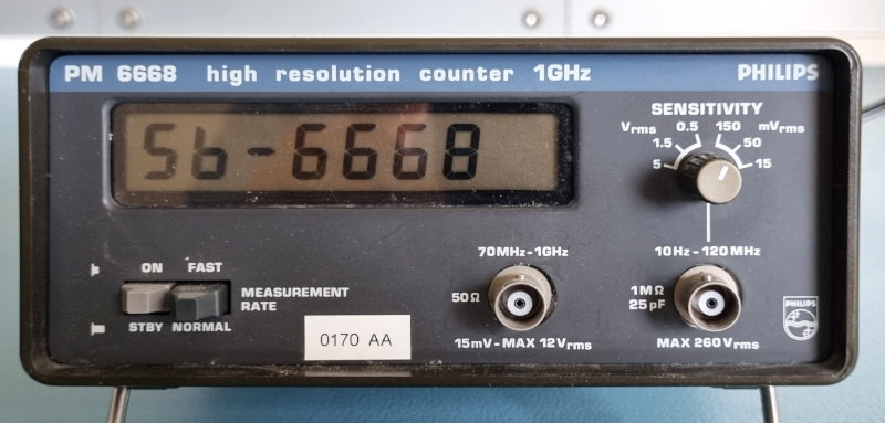 My PM-6668, with my own version of the firmware, shows its name as a splash screen
I have always loved frequency counters, probably because most of them have lots of digits to display.
When I started at my first real job, back in 1982, I noticed they had a very special frequency counter.
Its resolution was always 7 digits, regardless of the magnitude of the measured frequency.
The model number of this frequency counter was the PM-6668, which is the exact same model as I was able to purchase from an old colleague many years later.
Apart from its constant resolution the size of the instrument is also quite remarkable.
It's just a small box, where many of the frequency counters of the day were 19" racks with a very loud fan in the back.
Back in 1996 I gave the counter a new brain, which allowed me to expand its capabilities. You can read all about it on my SB-6668 project page.
The SB-Bus still functions today, although its usefulness of its remote control is now dwarfed by the capabilities of internet enabled devices. Therefore I do have plans to retire the SB-Bus in favour of the MQTT protocol. Hopefully I can find the time soon to make that transition to this counter, and to many of my other instruments.
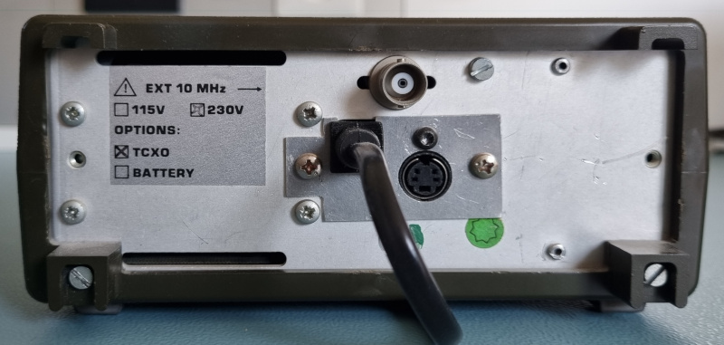 Fitted options and modified power input
As you can see from the picture above my PM-6668 is fitted with a TCXO, a Temperature Controlled Crystal Oscillator.
This means that the temperature of the reference crystal is kept at the same temperature at all times, making the frequency much more stable.
That's why you should allow the instrument to warm up to achieve the best possible accuracy.
B.T.W. I was amazed about the accuracy of this TXCO when I calibrated the oscillator of my bedside CMOS clock.
I haven't checked it against a rubidium standard or an GPS disciplined oscillator yet, but judging by the results I got with this clock I have full confidence in its accuracy.
In the past I was also able to verify the accuracy by draping the input probe over an old fashioned TV set, way back when analog TV broadcasts were still available.
This input probe picked up the line frequency of the picture which was kept exactly at 15.625kHz by the TV stations.
Part of my SB-Bus modification required an SB-Bus connector to be mounted somewhere. That was a bit of a challenge, because the rear pannel is completely occupied by the power transformer and the TXCO on the inside. So I had to replace the IEC power input connector with a fixed power cord to make room for one SB-Bus connector. Ideally there should have been two, to allow daisy chaining multiple instruments, but there simply wasn't enough room for that.
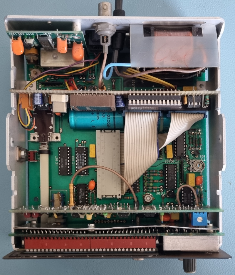 The inside of the counter after inserting the PCB with the new brain
The white DIL socket, with the two ribbon cables coming out of it connects the PCB with the new brain to the counter. This PCB replaces the original 8048 microcontroller, allowing the instrument to do much more than plain frequency counting. More details about the new capabilities can be found on the SB-6668 project page from 1996.
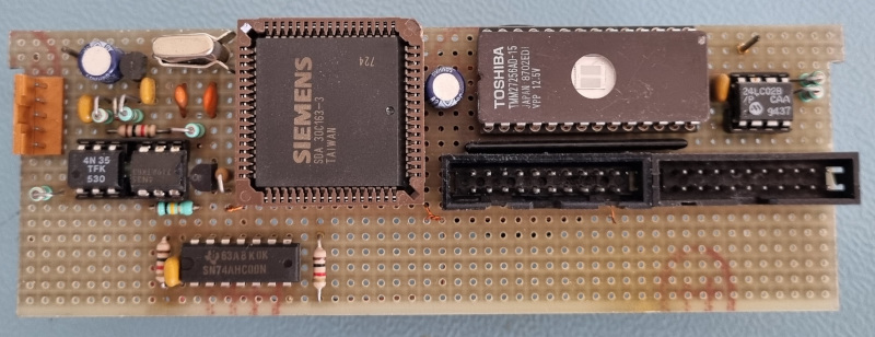 The CPU which forms the new brain of my counter
Here is a picture showing the PCB holding the CPU which forms the new brain of my counter.
Back in 1996 microcontrollers with erasable/programmable memory were very rare and probably very expensive.
That's why my solution was to repurpose a CPU from a scrap TV set, which required an external IC which held the program, the one with the window in it.
The window can be used to erase the program from the EPROM, so it can be reused with a different program.
Typically you would write your program, burn it into the EPROM with a special programmer, place the EPROM on the target system, try the program out, debug it, erase the EPROM by placing it under ultraviolet light for about half an hour and try again, and again, and again....
Obviously this way of programming had some disadvantages.
First of all, erasing the EEPROM every iteration was very time consuming.
A better equipped hobbyist would have multiple EPROMs which he could erase simultaneously, while writing to a few other ones which were erased previously.
So that problem is solved.
But there's another problem.
It is not uncommon that you would have several hundreds of iterations before the program was completed with all the bugs solved.
IC sockets are not designed for that kind of abuse.
This problem could have been solved by using a temporary ZIF socket (Zero Insertion Force socket), the same type which was used on a typical EPROM programmer.
This was exactly the way I started programming microprocessors and microcontrollers back in the eighties.
But I soon realised that there was some room for improvements.
So I've designed and built a few EPROM emulators.
I have documented only one of them on my projects page.
An EEPROM emulator is simply a RAM memory which can be reprogrammed without taking it out of the target system.
That way you can try out new versions of your program instantly, without the burning, swapping and erasing steps.
The only disadvantage of an EPROM emulator is that its contents will not survive a power down.
So at the end, when the program is finished, it is finally burned into a real EPROM to complete the programming.
And yes, officially you should shield the window of an EPROM to prevent accidental erasure by exposing it to lots of sunlight. I'm usually too lazy to bother about this, after all the circuit is placed in a dark box for its entire life anyway.
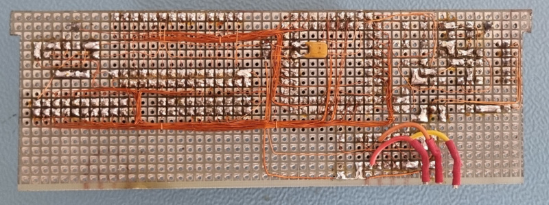 And that's the way I've built it
Nowadays you can get a PCB made from China for next to nothing.
This was totally different back in 1996.
That's why I've always built my projects using pad boards and Roadrunner wire.
Apart from short lead times this way of working has another benefit, you can design and test your circuit as you go.
No one will spot the bodges you'll have to add to make it work.
B.T.W. The three wires sticking out on the bottom allow me to select between the internal and external clock reference source using the built in menu, without opening the device.
 Inside the PM-6668. Click to enlarge the picture.
And this is what the inside of the PM-6668 looks like, with the prescaler and the CPU removed. The counter itself consists of just 2 handfuls of ICs, quite an integration achievement for the late seventies.
In the top left corner you see the TCXO module, with the yellow adjustment trimmer on the left of it.
I doubt I'll have to tweak the frequency very much if I'll ever get to building a GPS disciplined oscillator.
If you look carefully you'll notice another trimmer on the main PCB in the top left corner.
That is the trimmer for the standard oscillator, which is disabled and replaced by the TCXO option, so adjusting that trimmer is useless.
The internal/external reference selection is originally done by placing a jumper on 2 pins of a 4 pin header.
This header can be found just North/East of the IC which is located just behind the power switch, just behind the orange capacitor.
The two big blue capacitors were still fine, after some 40 years of almost constant service. I have kept my counter running 24/7 at least from 1996 onwards. The 5V regulator is mounted to the side of the chassis on the left, next to the power switch.
Judging by the date codes of the ICs I expect my instrument to be built at the end of 1980.
The wire which is hovering above the power switch is part of my enhancements.
It carries the SB-Bus signals from the rear connector to the CPU PCB.
Another, less obvious modification is done to the rate switch.
Normally this was a latching switch, which means that it would remain in the position you set it to.
This rate switch is now used as a menu switch, which is a momentary switch, it always returns to the off position.
A little spring has been removedfrom the switch, which performed the latching operation.
You can't see that in the picture because the display PCB sits above it.
I had to solder a little pin to the last contact of the switch, and bend this pin to cover the hole at the end of the switch.
This prevents the sliding mechanism of the switch from falling out of the back of the switch if you push the switch too hard.
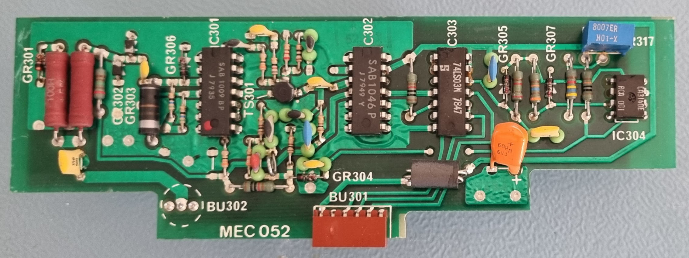 The 1GHz prescaler of the PM-6668. Click to enlarge the picture.
I own the PM-6668 model, which features a 1GHz prescaler. That is the only difference between the PM-6668 and the PM-6667, which lacks this prescaler.
