The SB-Bus Driver
Let's start with the easiest part of the SB-Bus, the hardware.
On the Master side you need a bus driver.
In case you don't understand the term Master yet, the Master is usually a PC controlling all devices (the Slaves) on the SB-Bus.
An SB-Bus driver is a simple electronic circuit which translates the electrical RS-232 signals to and from SB-Bus signals.
The TxD signal from the RS-232 port must be amplified to enable it to drive multiple LED's in the opto-couplers of the Slave devices.
And the signals coming back from the Slaves are transformed back to proper RS-232 levels before they can be accepted by the RxD pin of the Master's RS-232 port.
You can see some examples of SB-Bus drivers with varying drive capacity elsewhere on my site. I've even built an SB-Bus Driver around a Raspberry Pi which allows you to control the SB-Bus from all over the world.
The Slave Interface Hardware
Now it's time to describe the Slave side of the interface. Let's consider what needs to be done:
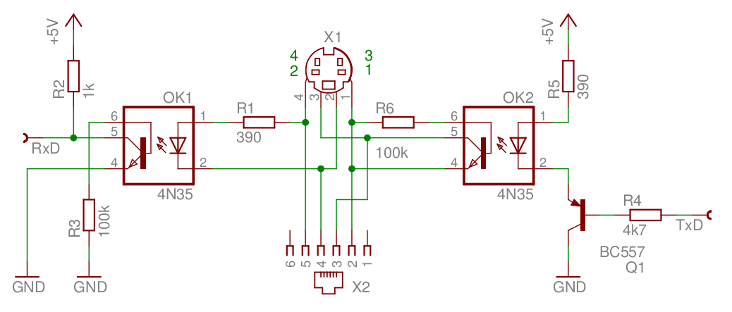
- Signals coming in from the SB-Bus driver (the connector in the middle in the diagram below) must be fed to the LED side of an opto-coupler. This is easy enough, in the diagram you can see that a simple 390Ω resistor is all that we need. All Slaves are connected in parallel with each other, so they all receive the same signal on their incoming opto-coupler. The other side of this opto-coupler is connected to the Slave's UART RxD input.
-
Signals going out from the Slave must also be electrically isolated from the SB-Bus.
A second opto-coupler is used to achieve that.
The output transistor of this opto-coupler is directly connected to the SB-Bus.
All output signals from all the Slaves are connected in parallel to each other, which effectively creates a wired-OR function.
The LED of the out going opto-coupler is driven by a transistor, which is used as emitter follower.

Basic SB-Bus Interface
Some remarks about this diagram:
I choose an emitter follower circuit to drive the transmit opto-coupler.
This way we can drive the LED without inverting the signal.
A normal NPN transistor would have invert the signal from the UART, which is high when it is in rest, resulting in the LED being constantly on.
A PNP transistor on the supply side could also be used to drive the LED without the need to invert the signal.
I deliberately didn't use this option because some UARTS have TTL levels on their outputs, which means that the high level does not exceed 3.5 Volts.
This would result in a continuous flowing base current through this transistor.
Many UARTS these days can even drive the 10mA, required for the LED directly, without the aid of an extra transistor.
The type of the opto-coupler is not very critical.
However, it should meet the most important property, which is the slew-rate.
Please take care that the output ramps of the opto-coupler are steep enough to avoid signal distortion.
I have had good results with the types 4N25, 4N35 and the CNY17-1.
To improve the slew-rate I connected a 100kΩ resistor between the base and emitter of the output transistor.
Please note that my experience with the CNY17-2, which is often used as feedback coupler in switched mode power supplies, was not satisfactory.
Do not connect pins 1 and 2 of the Mini DIN plug together, otherwise you won't be able to use a passive SB-Bus Driver. The +5V and GND are the power rails of the Slave. Please note that they are totally electrically isolated from the SB-Bus side of the system by means of the Opto-Couplers. Other supply voltages can also be used, however you may have to tweak some of the resistor values a bit.
In the early eighties crimp tools were rather expensive.
At least they were for me anyway.
So I chose to use the cheaper Mini-Dim-4 connectors for the SB-Bus.
They are small and relatively cheap.
However especially the plugs are pain in the backside to solder.
If I had to do it all over again I would have opted for the RJ11 connector instead.
Those plugs are even cheaper and much easier to assemble than the Mini-Din-4 plugs.
But not to worry, as long as the SB-Bus driver is equipped with both types of connectors, the can coexist on the save bus system peacefully.
So for new devices I would recommend you to use the RJ-11 connector, instead of the Mini-Din-4 connector.
Surely you don't have to use both types on one slave.
If you equip every slave with two connectors connected in parallel allows you to daisy chain multiple slaves together. Use either 2 Mini-Din-4 connectors or 2 RJ-11 connectors. Using one of each doesn't make much sense.
Take great care with projects that are directly connected to high voltages, e.g. measuring instruments. Electrical isolation is particularly important in those projects. Take heed to use a wide enough isolation area between the SB-Bus side and the "live" side of the instrument.
The SB-Bus Connector
More than 20 years ago I thought it was a good idea to use mini-DIN plugs for my SB-Bus devices. The same 4-way plugs are used for S-VHS connections, which somehow guaranteed availability. These plugs are both small and affordable.

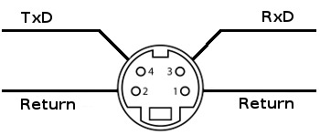
Master connector front view

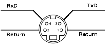
Slave connector front view
The diagrams above show the Mini-Din-4 connectors for both sides of the bus.
Swapping the RxD and TxD terminals on the Master connector enables you to connect all Slaves with simple straight through cables.
Please note:
The return terminals on the Slave side may not be connected together!
However it is no problem to connect the return terminals on the Master side together.
It is highly recommended to implement two SB-Bus connectors per Slave device. Both connectors should be connected in parallel with each other. This way it is extremely easy to daisy chain multiple devices to the SB-Bus driver.

Master connector front view

Slave connector front view
The diagrams above show the same situation for the RJ-11 connectors. For new devices I highly recommend these, as they are cheaper and the cables for it are much easier to assemble.
