UTP Cable Tester
Warning!
This design is some 25 years old by now.
Although it will still work, I recommend you to buy a ready made cable tester, unless you enjoy building one your self, even if it'll cost you much more than one you can buy ready made.
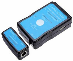
Nowadays cable testers like this can be bought for as little as €10, give or take a little.
That's far less than what you'll have to spend on parts alone if you want to build one yourself.
Feel free to read this page to find out how these things actually work, even if you are going to buy a ready made device.
The UTP Cable Tester can be used for many purposes.
Mainly to test a UTP network cables of course.
However it can also be used to find the right cable in a large bundle of identical looking cables.
In fact the circuit can be used or adapted to test any type of cable of any number of wires, provided that the tester is equipped with the appropriate connectors.
The UTP Cable Tester consists of 2 tiny boxes that have to be connected to each end of the cable under test. One of the boxes contains a signal generator, powered by a standard 9V battery. The other box contains 8 LEDs which indicate the cable's condition.
The principle of operation is very simple: A good cable will show a single walking light. However when the lights are lit out of order you'll know that some wires have been switched in one or both of the connectors. If one or more lights don't light up at all you'll know that one or more wires are cut. If two or more lights light up simultaneously you'll know that two or more wires are shorted together.
This is only a simple tester and therefore it can not detect separated pairs.
Even if all pins are connected, showing the expected walking light pattern it does not automatically mean that the pairs are still pairs in the cable.
Separating or mixing pairs will cause network problems on higher speeds and longer cables.
The UTP tester will not indicate such fault conditions!
Please have a look at my knowledge base to learn the proper way to wire a UTP cable.
Some network adapters and network switches have an auto polarity mode. This means that you may switch the white and coloured wires of a particular twisted pair without causing problems. A cable with wires 1 & 2 switched or 3 & 6 switched will indicate false on the UTP Cable Tester but might still function in some cases. It is not recommended to rely on the ability of the network adapter and network switch to sense the polarity though. When one of the devices is replaced by an other one after a while you may be in for a surprise.
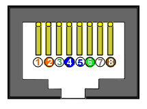
The display box has 3 RJ-45 connectors. The first one, marked 1:1, is intended for testing Straight Through or so called Patch cables. The second one, marked Xll, is used for testing 10baseT and 100baseTX Cross cables. The third one, marked XX, is used for testing 100baseT4 cross cables.
The Signal Box
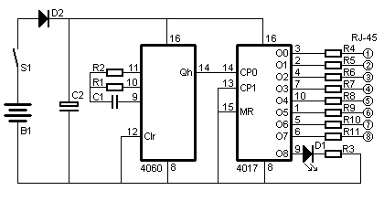 The Signal Box is powered by a 9V battery B1 which can be switched on and off by switch S1.
Diode D2 protects the circuit in case the battery is connected the wrong way up.
Current drain is minimal, approximately 5mA, which ensures quite a long battery life.
The IC 4060 generates a low frequency at its output.
The exact frequency is not that important, as long as you can identify signals in the wrong order on the Display box.
I choose a frequency of about 3Hz, resulting in a total loop time of approximately 3 seconds.
You may change the frequency by changing the value of C1 to suit your own needs.
This low frequency is fed to the input of the IC 4017, which is a decade counter.
It has 10 outputs, only one of which will be high at any time.
Every time the counter receives a low to high transition on its clock input it advances to set the next output high.
It has 10 stages, and we need only 8 LEDs on the Display Box.
One of the remaining stages is used to flash an LED on the Signal Box to indicate that it is functioning.
The 10th stage is obsolete, and no LEDs will be on during that time.
This way a short pause is introduced on the light pattern on the Display Box.
If you want you can use the 10th output to test the shield of an STP cable.
In that case you'll need an extra resistor, LED and diode in the Display Box.
The resistors on the outputs must limit the current flow and still leave some voltage to drive the affected LEDs in case 2 wires are shorted.
I could have used a programmable controller like a PIC16F84 or AT89C1051. The program would be quite simple. I deliberately chose the discrete approach though for a few important reasons:
- It is cheaper than a micro controller.
- It consumes less supply current.
- It does not require a programmed device, making it easier for all of us to build it.
- It does not require a regulated voltage, making the power supply very simple.
But if you are only a little familiar with micro controllers, feel free to program the Signal Box in a processor of your choice.
The Display Box
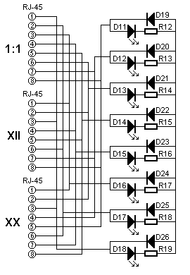 The Display Box contains 3 RJ-45 connectors.
The first connector, marked 1:1, is used to test Patch cables.
On the second connector, marked Xll, the wires 1 & 2 are swapped with the wires 3 & 6.
It is used to test normal Cross cables for 10baseT and 100baseTX networks.
The third connector, marked XX, is used to test 100baseT4 cables, which have all 4 pairs of wires crossed.
The circuit can be divided into 8 identical parts which all contain an LED, a normal diode and a resistor.
The anodes of all diodes are connected together creating a virtual ground.
Remember that only one output of the 4017 was high, all other outputs are low at that time so there will always be enough sinking capacity for the LED current.
The LEDs are connected to the RJ-45 connectors in a row.
Pin one to D18, pin 2 to D17, etc.
This order is very important for it will determine the walking behaviour of the lights during testing.
The resistors are used to limit the current through the LEDs to about 4mA, which is enough for modern LEDs.
I deliberately didn't use just one resistor for the whole circuit.
In normal conditions it wouldn't be a problem if I did.
But when 2 wires are shorted 2 LEDs would have to share their current by this one resistor, creating a higher voltage drop reducing the current through the LEDs even further.
Bill Of Materials
| B1 | 9V Battery |
| S1 | Any kind of on/off switch |
| C1 | 10nF |
| C2 | Elco 47µF / 16V |
| R1 | 56 kΩ |
| R2 | 1 MΩ |
| R3 | 1.8 kΩ |
| R4..R11 | 8 times 470 Ω |
| D1 | LED of your choice |
| D2 | 1N4148 |
| 4060 (any manufacturer will do) | |
| 4017 (any manufacturer will do) | |
| 4 RJ-45 connectors | |
| D11..D18 | 8 LEDs of your choice |
| D19..D26 | 8 times 1N4148 |
| R12..R19 | 8 times 1.2k Ohm |
Practical examples
I've created some animated pictures to demonstrate the use of the UTP Cable Tester. Too bad you can't print the animation ;-)
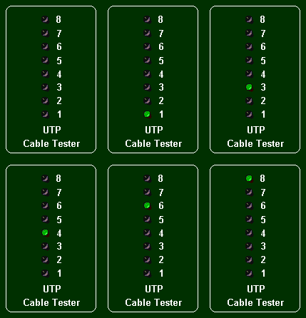
This first example shows the pattern for a good cable. All wires are connected, none are shorted, none are swapped.
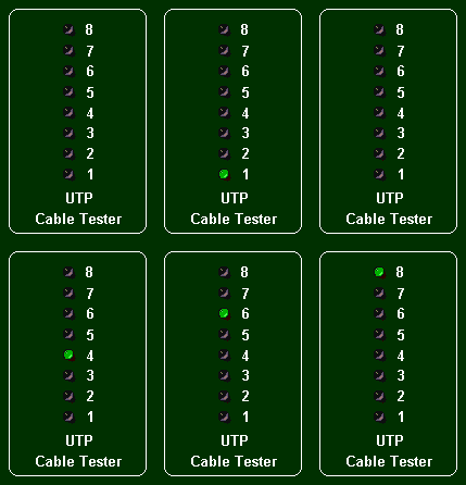
LED 3 doesn't light up in this example, which means that wire 3 is cut.
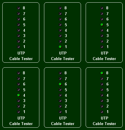
In this example we can see that the LEDs 3 and 5 light up out of order. LED 5 lights, when LED 3 should have, and LED 3 lights when LED 5 should. This indicates that the wires 3 and 5 are swapped.
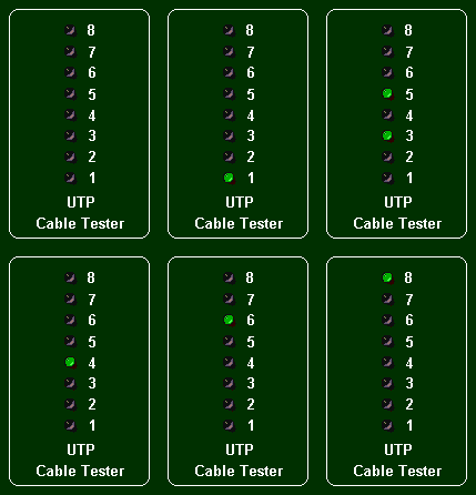
This final example shows that the LEDs 3 and 5 light simultaneously, indicating a short between the wires 3 and 5. Notice that both LEDs light up twice. Once if only LED 3 should light up, and once when only LED 5 should light up. In reality both LEDs will light up with lower intensity than normal because the voltage coming from the IC is halved.
If an error is indicated by the UTP Cable Tester, it may be a bit tricky to find the faulty wire(s) on Cross cables.
The wire number indicated by the LEDs are the wires seen from the connector at the Display Box's end.
Testing the other way around can show other wires being faulty!
This is normal behaviour though, and is the nature of Cross Cables.
 Warning!
This design is some 25 years old by now.
Although it will still work, I recommend you to buy a ready made cable tester, unless you enjoy building one your self, even if it'll cost you much more than one you can buy ready made.
Nowadays cable testers like this can be bought for as little as €10, give or take a little.
That's far less than what you'll have to spend on parts alone if you want to build one yourself.
