UTP Ethernet Cables
Ethernet is often used to build a network of computers in home and office situations.
Today UTP Ethernet is the preferred method to connect the computers with the rest of the network.
Several standards exist to accommodate different transfer speeds.
The basics remain the same however, no matter what speed is used.
Three network speeds are common today.
10base-T networks have a transmission speed of 10Mbits/second.
100base-TX networks, which have a transmission speed of 100Mbits/second.
And 1000base-T, or Gigabit networks have a transmission speed of 1000Mbits/second.
For Gigabit networks you need at least CAT-5e or CAT-6 cable.
Cable Properties
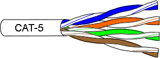 UTP stands for "Unshielded Twisted Pairs".
Such a cable consists of 4 pairs of wires, where each pair is constantly twisted along the total length of the cable.
This twisting is very important, for it ensures interference immunity and low radiation emission.
The overall quality of the cable is very important, especially if you want to run the network at 100Mbit/sec and beyond.
For 10Mbit/sec speeds you can use CAT-3 cables, but if you want to run your network at 100Mbit/sec CAT-5 cable is required.
My advice is always to use at least CAT-5e cable quality, regardless of your current network speed.
Upgrading in the future will be so much easier if you don't have to replace all your wiring.
Connectors
UTP Ethernet uses RJ-45 connectors.
These are crimp connectors, with 8 contacts.
They are quite similar to telephone connectors but have a few more contacts.
You need a special crimping tool to mount the connectors to the cable.
If you intend to make more than a few cables in the future you'd better buy a decent crimping tool.
The plastic versions usually don't live very long.
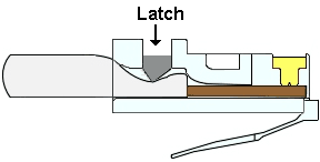
When you crimp the connector to the cable be sure that all wires run all the way to the end of the connector and that the cable's sleeve is caught by the latch.
Connections
The actual communication over a UTP Ethernet is done over two wire pairs. One pair is used for sending (TX), the other pair is used for receiving (RX). The TX side from one end of the cable is connected to the RX side on the other end, and vice versa.
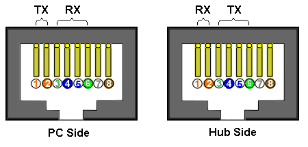
Therefore we have to cross the pairs if we want to connect two computers together.
Connecting more than two computers together this way is not possible.
We need a Hub or Switch to do the crossing for us.
Connecting a computer to a Hub or Switch does not require the pairs to be crossed because the crossing is done inside the Hub or Switch.
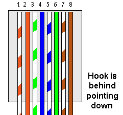
The two pictures above show you the signals on a PC connector and on a Hub connector, seen from the outside.
Notice that the two pins in the middle (pins 4 and 5) and the right most pins (pins 7 and 8) are not used.
For Gigabit networks all 4 pairs are used.
Straight Through Cable
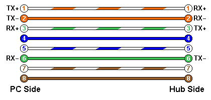
The most commonly used cable in UTP Ethernet networks is the straight through cable, a.k.a. the patch cable.
This type of cable is also called a patch cable because it is often used to make connections on patch panels.
The straight through cables are only used to connect a computer to a Hub or Switch.
To connect 2 equal devices together (computer to computer, or Hub to Hub) you should use a cross cable.
Some Hubs have an upload port to receive a connection coming from another Hub.
There you should use a straight through cable again, because the crossing is done on the special upload port.
Some hubs came with a switch at the back of the device to make one of the ports a cross connection or a strait through connection, giving the same effect as a special uplink port.
Intelligent Switches may even auto switch between straight through and cross depending on the requirements.
With these Switches it doesn't matter any more what type of cable you use.
As you can see in the picture the cross over from TX on one side to RX on the other side is done by the Hub, where TX and RX have swapped positions compared to the computer side.
In reality every coloured pair is twisted along the length of the cable, but I have untwisted them in the picture for clarity (and it's easier to draw too ;-).
The blue and brown pairs are not used for 10baseT and 100baseTX networks.
100baseT4 and Gigabit networks use all 4 pairs.
Also notice that the colour coding of the blue pair is swapped in comparison with the other colours to achieve alternate full and half-coloured wires for all 4 pairs.
Cross Cable
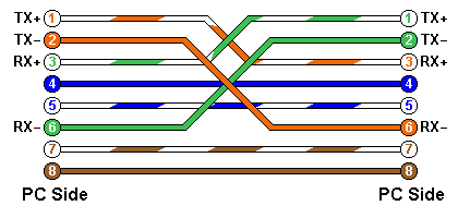
A cross cable should provide the necessary crossing from TX to RX if both devices are of the same type (computer to computer, or Hub to Hub).
As you can see in the picture the TX wires are crossed to the RX wires on the other side of the cable.
Please note that the blue and brown pairs are connected straight through on a cross cable.
They are never twisted.
In theory they should also be crossed for Gigabit networks.
However Gigabit network cards will never need cross cables any more, because they are intelligent enough to manage the crossing of TX and RX themselves.
Testing
Trouble shooting cables is a tedious job, especially if your wires run through the entire building. So you best avoid errors. But if there were an error somewhere, it would be nice to have a cable tester. Of course you can test the cable with an Ohm meter or continuity tester, but with just a few components you can build a comfortable cable tester. This tester can also come in handy to find a particular cable in a large bundle of cables. I have designed an easy to build Cable Tester that can find almost all possible problems in a cable.

