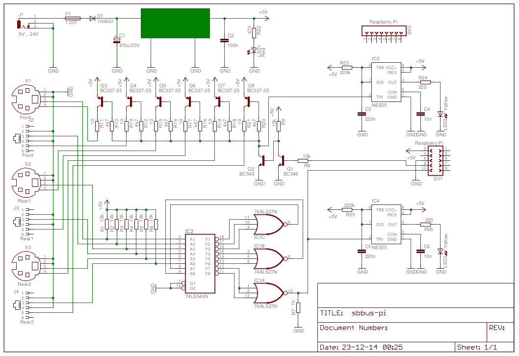
Circuit Diagram

Click on the diagram above to get a larger PDF version, which allows you to see more details.
The circuit of the Pi-Bus Driver can be divided into 3 main parts. The power supply, the output circuit and the input circuit.
The Pi-Bus Driver will drive 6 outputs, which can drive about 10 SB-Bus devices each, giving a grand total of 60 different devices.
Even after some 30 odd years I don't own that many yet.
In the beginning I thought it was a good idea to use those 4-pin mini DIN connectors for the SB-Bus.
They were easy to get and fairly easy to solder together.
Now I think it is more appropriate to use RJ-11 plugs to connect the SB-Bus slaves to the SB-Bus master.
Not only are they a lot cheaper.
Cables are a lot easier to construct.
The only thing you'll need though is a proper crimping tool.
Fortunately they cost just a fraction of what they used to cost back in the old days.
Therefore I use both plug types on this Pi-Bus Driver now. The old 4-pin mini DIN plugs for the legacy devices and the RJ-11 plugs for any new devices I'm going to build.
Raspberry Pi Connector
SV1 is the Raspberry Pi expansion connector.
I only need the first 10 pins, that's why the connector is this short.
The Raspberry Pi is mounted upside down with its expansion connector directly fitted into SV1.
In case you have the first revision of model B you won't have any mounting holes in the PCB.
That's where SV2 comes in.
You don't need any of its signals, it's only there for mechanical support.
Power Supply
Without a power supply nothing goes.
I use a simple DC-DC converter I've bought from Ebay.
This converter takes just about anything from 9V to 35V, but due to C1 only 24V is the maximum in my case.
I don't bother about that because I run the Pi-Bus Driver from a 9V power supply.
D1 is simply a protection against reversed polarity of the input voltage.
The rest of the power supply circuit is as simple as pi.
I could have used a standard 5V power supply. But this solution is cheaper and less critical on the input voltage and it doesn't run hot.
Output Circuit
A total of 6 outputs have to be driven by an equal number of output transistors (Q3 to Q8).
Each output transistor has its own 10Ω protection resistor and is capable of driving 100mA with ease, ensuring the capability to drive up to 10 SB-Bus devices per output.
The output transistors are driven by the double inverters Q1 and Q2.
They also serve as level converters, converting the 3.3V logic of the Raspberry Pi to the 5V logic of the output stage.
IC3 is used as a pulse stretcher, which drives the TxD LED on the front panel.
Input Circuit
Each one of the 6 inputs are fed to IC2, which is basically an octal Schmitt-Trigger inverter.
The 6 inverted outputs are added together on IC1B and IC2B.
Their outputs are again inverted by the 2 remaining inverters of IC2, after which these two signals are again added together to form the combined input signal.
In rest all inputs are high, resulting in a high output on pin 12 of IC1A.
If at least one of the inputs is drawn low, the output of pin 12 of IC1A is also drawn low.
So pin 12 of IC1A simply follows any of the input's signals.
LS TTL devices have a very poor pull up transistor circuit. Therefore the output voltage will rarely exceed 3.6V, even on 5V logic devices. R7 puts a little more load on the output, which reduces the output swing of this IC to roughly 3.3V. The Raspberry Pi will happily accept this logic high level.
The combined output is fed to IC4, which stretches the pulse again to be displayed by the RxD LED on the front panel.
Construction


Of course there are many ways to construct the Pi-Bus Driver.
I love these small aluminum boxes which I have salvaged from some old Nokia phone test tools.
The board space in these boxes is 10 x 10 cm, which is, as you can see in the picture quite enough to fit all parts.
True, it was a bit of a puzzle to squeeze all the connectors in.
But by using both sides of the PCB I managed to put 4 SB-Bus connectors on the rear panel.
The front panel isn't that crowded.
There only 2 SB-Bus connectors are placed for portable equipment.
3 LEDs on the front panel show the status of the power supply, and the TxD and RxD pulses.
Incidentally the TxD LED will light up constantly when you halt the system.
It is not by design, but it indicates when it is safe to remove the power once the system is halted.
The dimensions of the box just allow the SD card to be inserted fully into the device, leaving no grip to take it out again.
Therefore I have provided for a small hole in the middle of the SD card slot.
Now I can take the SD card out with a pair of pliers.
This prevents me from removing the SD card accidentally.
