Building The Hardware
In my case the whole circuit fits on a piece of pad board measuring 57.5 x 100 mm. A PCB of these dimensions can find a suitable place in the back of the meter, next to the mains connector. This place is originally reserved for the rechargeable battery. You can easily fasten the interface PCB using the slits in the main PCB.

Before upgrade
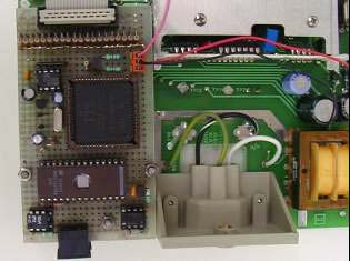
After upgrade
It may be necessary to modify the shielding plate a little to make room for the interface PCB.
The SB-Bus Connections
 If you look at the back of the meter you will see two columns, one on each side of the mains connector.
The one to the right of this power connector is just large enough to facilitate 2 mini-DIN connectors.
It is as if Fluke intended these columns to be used by the SB-BUS back in the late seventies.
You need to drill 2 holes with a diameter of 15 mm in the back of the meter's cabinet, just opposite of the two connectors.
It may be tricky to pinpoint the exact location for the holes, but it should work if you start by drilling small holes.
Please remember that the meter's main PCB is hanging upside down in the cabinet, so please be careful when choosing the place to drill!
 You'll have to let the 2 mini-DIN connectors extend about 4 mm out of the back edge of the PCB to make them fit perfectly into the little column of the cabinet.
The mini-DIN connector must be placed exactly 28 mm from the plastic part of the mains connector.
As you can see in the picture the 2 connectors are placed on top of each other to squeeze them both into the tight column of the cabinet.
To achieve this, the raised connector is placed on a tiny PCB measuring 57.5 x 35 mm. This separate PCB is best mounted flat on the meter's main PCB, with the interface PCB above it. I used 25 mm long screws and 14 mm long spacers to mount the interface PCB to the meter's main board. Naturally you'll need some washers to prevent the screws from squeezing themselves through the huge slits in the meter's main board.
Safety First
Safety needs special attention when fiddling about with the internals of a multi-meter.
Remember that the meter's Common terminal may be lifted up to 500V above ground level!
And since the interface ground rail is connected directly to this Common terminal the interface will be raised above ground level too.
Therefore the opto-couplers should safely insulate this 500V.
The opto-couplers which are used in this circuit are specified to insulate up to 2500V, so that's not really a problem.
But what could be a problem is the way you mount them.
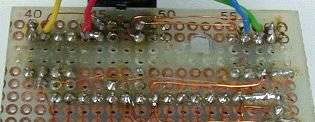 I've placed the opto-couplers at the back edge of the PCB, one on each side of the mini-DIN connector.
This way no signals have to be passed underneath or near the opto-couplers.
It is also important to remove all the copper pads from the pad board underneath the opto-couplers to increase the spark gap distance.
This can easily be done by heating such a pad with a soldering iron, and then wipe it away by applying some moderate force to the soldering iron.
This is not all yet!
While mounting the interface as described above it may happen that one of the screws touches the earth ring surrounding the mains connector.
Either you use a plastic screw here, or you should remove some copper pads from the interface PCB near the screw.
With all these efforts it should be safe to operate the meter together with the SB-Bus.
The Processor And The EPROM
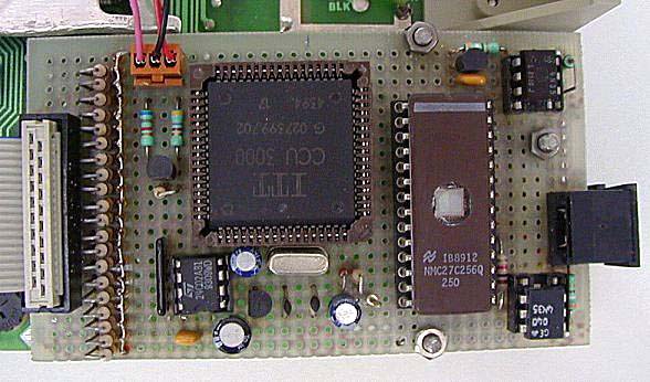
The EPROM will find a suitable place right behind the two opto-couplers. It will almost fill the PCB from side to side but it will still leave some room on either side for two of the 3 screws. Next to this EPROM you can mount the CCU, aligned at the inner side of the PCB, with pin 1 facing outward. This way all connections can be as short as possible. On the rear side you'll have the connections to the EPROM, and on the front side you'll have the I/O connections. Placing the CCU close to the inner edge of the PCB assures enough room for the EEPROM, the crystal oscillator, the power supply and reset components.
Connections To The Interface PCB
The PCB contains 2 internal connectors, not counting the mini-DIN sockets. One of them is a 20-pin boxed header, carrying all segment signals. The other one is a 3 pole connector, carrying +12V, GND and the signal to the BT indicator.
The 20-pin boxed header is best placed along the short side of the PCB.
The 20 series resistors and substrate protection diodes can be lined up in two rows directly behind this connector.
As a reference, pin one of the boxed header is pointing towards the middle of the meter.
All diodes can best be mounted with their cathodes through the PCB and their anodes pointing up which makes it easier to tie all anodes together.
Finally the 3-pole connector will find a nice place in between the row of diodes and the CCU.
Wiring The PCB
The wiring of the PCB is not very critical.
Although extreme care should be taken when soldering the double row of pins to the CCU3000.
You best connect all the pins on the outer rows of the socket first, and then the inner rows.
That way you don't have to solder pins anymore that are already covered by other wires.
With a balanced amount of care and patience, and the proper tools of course, I don't foresee any problems.
I used Road-Runner wiring to connect all signal lines.
Fix all these wires with the power rails, using slightly thicker wires (e.g. 0.3mm²).
The Segment Cable
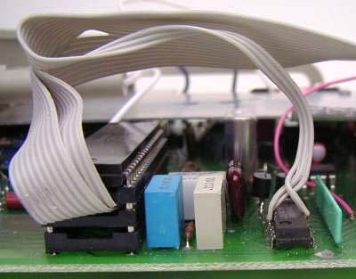 The purpose of the segment cable is to connect the interface to the required segments of the meter.
A total of 17 wires are to be connected to the main IC.
Unfortunately this is also the IC that is very likely the first one to die when excessive voltages are applied to the meter's inputs.
That's why I don't recommend to solder these 17 wires directly to this IC, for that would make it very difficult to replace it.
Fortunately the main IC is placed in a socket on all models that I have seen. I have built a piggy-back system, with two 40-pin sockets stacked together. I connected the 17 wires to the this piggy-back socket, and placed it in between the existing socket and the main IC.
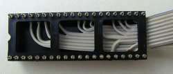 Preferably use 2 sockets with twisted contacts, because the pins are much stronger on those models.
Connect all 17 wires as close as possible to the plastic carrier of one of the sockets.
The wires should be soldered to the thickest part of the pins, so that the thin parts of the pins remain untouched by solder!
After that you can put this socket into the 2nd socket, both securing the bundle of wires, and preventing possible shorts between the cable and the socket of the meter's main board.
The 3 remaining wires (18, 19 and 20) have to be soldered directly to the pins 11, 4 and 3 of U6 on the main board respectively.
The length of the flat cable to use is about 15 cm.
Below you'll find a wiring table for the 20-wire flat cable:
| Meter pin | Header pin | Segment |
| U3 - 4 | 17 | b3 |
| U3 - 5 | 16 | a3 |
| U3 - 6 | 15 | f3 |
| U3 - 7 | 14 | g3 |
| U3 - 8 | 13 | e3 |
| U3 - 11 | 12 | b2 |
| U3 - 12 | 11 | a2 |
| U3 - 13 | 10 | f2 |
| U3 - 14 | 6 | e2 |
| U3 - 16 | 5 | b1 |
| Meter pin | Header pin | Segment |
| U3 - 17 | 4 | f1 |
| U3 - 18 | 3 | e1 |
| U3 - 19 | 2 | OL |
| U3 - 20 | 1 | pol |
| U3 - 22 | 9 | g1 |
| U3 - 23 | 8 | a1 |
| U3 - 25 | 7 | g2 |
| U6 - 3 | 20 | dp1 |
| U6 - 4 | 19 | dp2 |
| U6 - 11 | 18 | dp3 |
The Finishing Touch
 The only thing left to be done is to connect the 3 wires of the 3-pole connector somewhere in the meter.
One of them has to be connected to the +12V supply, coming directly from the rectifier.
You can solder this wire directly to the cathode of CR9.
This is the diode which is closest to the meter's on/off switch.
The second wire must be connected to the meter's ground plane.
It is very important where to connect it, don't be tempted to connect it just anywhere, for supply currents to the interface might interfere considerably with the meter's accuracy!
The best place to connect this wire to the ground plane is as close to the main tank capacitor as possible.
Between the two capacitors C30 and C31 you'll find a solder pad, which can be used as a suitable ground connection.
And the last wire, intended to control the BT indicator, must be connected to pin 8 of U6.
If you follow the track from this pin you'll pass a resistor network where it ends in a soldering pad, which is a suitable place to connect this wire.
When you've followed these instructions carefully you may now close the meter and start using it again, but this time with some nice extra features.
Please remember that the SB-Bus address of a maiden device will be set to 254 ($FE).
You should change this address as soon as possible to avoid conflicts with possible other SB-Bus devices.
