AVR STK200/STK300 ISP Dongle
In advance to my first AVR hardware project I needed an ISP programming dongle in order to burn the software into the AVR's FLASH memory.
Apparently there are several programming dongles available out there, like the Altera compatible dongle, Jesper's original, and the Atmel STK200 and STK300 dongles.
I chose to use the original Atmel dongles.
Atmel produced a couple of evaluation boards for their AVR family of processors.
The STK200 could be equipped with one of the AVR type of processors, while the STK300 was build around an ATMega processor.
Both evaluation boards used a very similar dongle.
They only differ in the position of the identification wire.
The circuit description will tell you more about this.
I didn't design this little project myself. I only include it on my site as a reference for my own personal use, though you may benefit from it too.
This particular ISP dongle is to be connected to a PC's LPT connector, if you still have a computer which has one of course.
It can be controlled by several versions of Atmel's AVR studio, but I found it more practical to use it with Claudio Lanconelli's excellent PonyProg while I was still using Windows.
Under Linux you could use the program avrdude to control the AVR ISP dongle.
Ubuntu users can install avrdude right from the standard repositories.
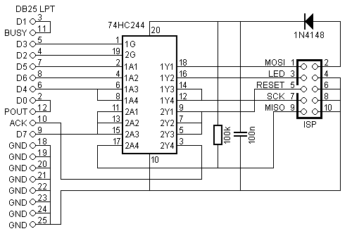
Circuit Description

 Not very complicated is it?
Well looks can be deceiving, because the diagram is far more complicated than absolutely necessary.
The interface could have been built even without any of the electronic components!
Why are they in there then?
Simple, to accommodate a real ISP mode of programming.
If the IC wasn't in there we would have to be careful with our target system.
We would have to take care that the circuit around the programming pins weren't connected to anything else than the ISP socket.
Well actually we still have to take some precautions when it comes to the SCK, MISO and MOSI pins in the target system.
For obvious reasons we must make sure they are never tied to VCC or GND while the system is in RESET by any other output device connected to these pins.
The 74HC244 is used as an "isolator" circuit when the AVR is not in programming mode.
In idle mode all outputs are tri-stated, as not to affect the operation of the target system.
When ISP mode is selected the bottom half of the 74HC244 is enabled, pulling the target system's RESET line low.
There were three buffers available for this task, which is a good thing because we may have to discharge the target system's reset capacitor with it.
Once the target system is in RESET we may assume that the SCK, MISO and MOSI lines are no longer loaded by peripheral circuitry on the target system.
Now it's safe to enable the top half of the 74HC244, driving the MOSI, LED and SCK lines of the ISP connector.
There are two short circuits on the DB25 LPT connector for identification purposes. The 2-12 short is the auto detect line for an STK200 dongle, while the 3-11 short is used as auto detect line for the STK300. Both shorts may be present simultaneously.
Before You Begin
Since parallel ports on computers are not very common anymore I think it’s only fair to point you to a better and perhaps cheaper alternative for an Atmel AVR programmer in the 21st century. For just a few Euros you can now buy a small USB programmer, ready made, delivered. However you may have to tinker around a bit to get it working. You can read all about it here.
Construction
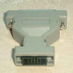
 The easiest way to build this dongle is to sacrifice a 25-way to 9-way D-Connector converter for the purpose.
Be sure though to obtain one that is not sealed so it can be opened.
Open the converter carefully, as not to damage the 4 latches which hold the two shells together.
Like always I've built the circuit on a piece of pad board, using the tried and tested road-runner wiring method. Here are a few tips you should follow in order to make life as easy as possible:
- Carefully align the pads of the pad board in between the narrow neck of the converter shells. Exactly 5 whole pads should fit next to each other. Failing to align the middle row of holes to the center of the narrow neck will eventually result in an out of center placed boxed header.
- The narrow end of the board should end exactly at the end of the narrow neck of the shells. This way the boxed header will fall as far back into the shells as possible, which increases its mechanical stability.
- The odd numbered pins of the boxed header are best put on the copper side of the board.
- The board should fit exactly between the two rows of the 25-way male D-Connector. Be sure the copper side of the board is on the side of the shortest row.
- Cut the pins 14, 15, 16 and 17 of the D-Connector away, to avoid short circuits between them by the underlying copper pads. Another way to avoid short circuits is to remove the pads that lie directly under the afore mentioned pin numbers.
- Do not use a socket for the 74HC244, because there is not enough room for it.
Following these tips should be your ticket to success. There may be a little space left around the boxed header when the two shells are put together again. If you like you can fill this space with a piece of plastic, but this is not absolutely necessary.
 In advance to my first AVR hardware project I needed an ISP programming dongle in order to burn the software into the AVR's FLASH memory.
Apparently there are several programming dongles available out there, like the Altera compatible dongle, Jesper's original, and the Atmel STK200 and STK300 dongles.
