6802 Nano computer
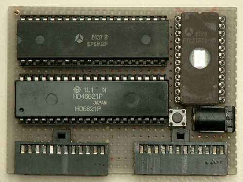
Back in 1993 I had some time to spare (those were the days), and I decided to build a small Single Board Computer.
This SBC was used to demonstrate the possibilities of such a small computer system here at the local computer club.
I also used it to do some experiments, e.g. with the I²C bus.
On its own the 6802 Nano Computer is nothing special.
It contains only 3 ICs: Micro processor 6802, I/O chip 6821 and an EPROM 2732.
Together with one of my Eprom Simulators this system can become a very easy to use experimental micro computer.
Some students have asked me for a small micro processor project.
I hope this small project will give them some inspiration to find new applications for the 6802 Nano Computer to impress their mentors with.
I've written a few small programs to demonstrate the use of the 6802 Nano Computer.
If you're a student in need of a project, please do yourself a favour and design a new application for the 6802 Nano Computer yourself!
Simply copying my project won't teach you anything.
And your mentors probably browse the internet too, so what grade do you think you will receive if he or she sees a remarkable resemblance between your project and mine?!
I deliberately don't include too many example applications for the 6802 Nano Computer to encourage you to create new projects on your own.
All examples are written using my freely available SB-Assembler which can be found elsewhere on this site.
Features:
- 6802 (a 6800 with 128 bytes RAM and clock oscillator)
- 6821 (16 GP I/O + 4 special I/O lines)
- 4kB of EPROM (up to 32k also possible)
- 1 MHz clock speed
- Relatively small size (for those days)
Circuit Description
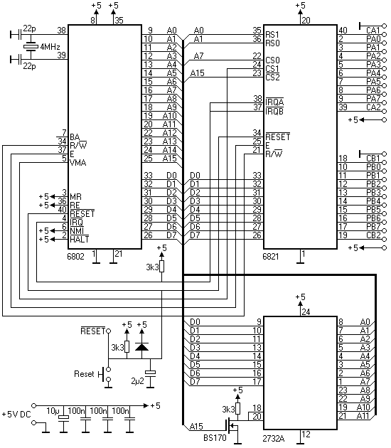
There is not much to be said about the circuit diagram. It is simply a matter of connecting all the Data and Address bus lines between the 3 ICs.
The EPROM's OE and CS lines are tied together and receive the inverted signal from the A15 address line.
A FET is used as inverting circuit here, although you may think of a dozen other ways to invert the A15 signal.
I used a 2732A EPROM in my version of the computer.
But if you intend to use the 6802 Nano Computer together with my Tiny Eprom Simulator you may also connect some more address lines to facilitate a 27C256 EPROM.
That way you don't need a special 32k to 4k adapter cable.
The address range of a 4kB EPROM is from $F000 to $FFFF, although it is mirrored all the way from $8000 to $FFFF.
Mirroring means that the same locations can be read from $8000 to $8FFF and from $9000 to $9FFFF, etc.
The address range of a 32kB EPROM runs from $8000 to $FFFF without any mirroring.
The addressing of the 6821 may require some explanation I think.
The address lines A0 and A1 are connected to the Register Select lines RS1 and RS0 respectively.
It is not a bug in the diagram, A0 is connected to RS1, and A1 is connected to RS0!
I can't really remember why I swapped these two lines 9 years ago.
Maybe I did it to make it possible to use one 16-bit move instruction to read or write both I/O ports simultaneously.
Address lines A7 and A15 are connected to the Chip Select lines.
This makes the four 6821 registers available at addresses $80 to $83.
Because of the partial address decoding these 4 addresses are mirrored all the way from $80 to $7FFF.
The table below shows you the address map of the 6821:
| $0080 | Data Register A |
| $0081 | Data Register B |
| $0082 | Control Register A |
| $0083 | Control Register B |
The address range $0000 to $007F is decoded internally in the 6802, and is assigned to the 128 bytes of RAM.
The reset circuit ensures a proper start-up of the system when it is powered up. The reset pin, above the push button, can be connected to the reset line of the Tiny Eprom Simulator. That way you can upload and start new software completely automatically.
I have connected the two output ports of the 6821 to two identical 12-way connectors.
These connectors can connect to a variety of interface boards, each tailored for a specific task or experiment.
I've mounted all the small components in between the IC sockets underneath the ICs.
That's why you can only see the three ICs, the reset push button and the connectors in the title picture at the top of this page.
In the left hand upper corner of the picture you can also see the RESET pin, which receives the reset signal from the Tiny Eprom Simulator.
I've deliberately used a ceramic resonator instead of a more traditional crystal because it is smaller and fits nicely in between the legs of the micro processor. It is not as precise though. As a bonus it also saves me two capacitors to ground.
Dice Game
 A pair of dice is the first small example application I present here.
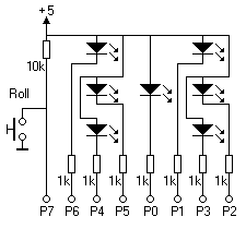
The interface is nothing more than 2 sets of 7 LED's, arranged in the form of two dice.
One push button per die completes the interface circuit.
The diagram shows the wiring of one of the two dice.
The circuit for the other die is exactly the same, and should be connected to the other output port of the 6802 Nano Computer.
You must push the buttons to "roll" the dice.
Internally the program constantly counts from 5 down to 0 for as long as the push button is depressed.
The counting speed is different for both dice to avoid synchronous behaviour of both dice.
This counter is freezed on the LEDs once the push button is released, thus creating a very easy random generator.
I think it is impossible to predict the counter's value in any way, making the result random enough for our harmless purpose.
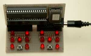
The rolling of the dice is simulated by a walking light on the LEDs for as long as the push button is down. The pattern on the left die rolls counter clock wise, while the right die rolls clockwise. This walking light is just for cosmetic purposes, and is in no way related to the roll's result.
Below you can see the program listing for this example.
The program is not very long, and shouldn't be too difficult to understand.
You can download the program and directly assemble it with the SB-Assembler.
The resulting file DICE.HEX can then be burned into a suitable EPROM.
;------------------------------------------------------------------------
;
;  DICE.ASM
;
;  Author: San Bergmans
;          www.sbprojects.net
;
;  Created for the 6802 Nano Computer at 29-8-1993
;
;  Demonstration program, rolling two dice
;
;------------------------------------------------------------------------

             .CR    6800                Select cross overlay
             .OR    $F000
             .TF    DICE.HEX,INT        Specify target file

;------------------------------------------------------------------------
;  Declaration of constants
;------------------------------------------------------------------------

DIE1            .EQ     $0000           Roll of die 1
DIE1_FLAG       .EQ     $0001           Die 1 rolling if <> 0
WALK_PAT1       .EQ     $0003           Walking pattern for die 1
DIE2            .EQ     $0004           Roll of die 2
DIE2_FLAG       .EQ     $0005           Die 2 rolling if <> 0
WALK_PAT2       .EQ     $0006           Walking pattern for die 2
WALK            .EQ     $0007,$0008     Walk delay counter
POINTER         .EQ     $0009,$000A     Pointer to retreive LED pattern

PIA_A           .EQ     $0080           Pia data register A (die 1)
PIA_B           .EQ     $0081           Pia data register B (die 2)
CON_A           .EQ     $0082           Pia control register A
CON_B           .EQ     $0083           Pia control register B

WALK_DELAY      .EQ     500             Delay time reload value

;------------------------------------------------------------------------
;  Reset and initialisation
;------------------------------------------------------------------------

RESET           LDS     #$007F          Reset stack pointer
                LDAA    #%0000.0100     Initialise PIA ports
                STAA    CON_A
                STAA    CON_B
                LDAA    #%0111.1111     b0..b6 are outputs b7 is input
                STAA    PIA_A            for both PIA ports
                STAA    PIA_B
                CLRB
                STAB    CON_A
                STAB    CON_B
                STAA    PIA_A
                STAA    PIA_B
                LDAA    #%0000.0100     Select data registers again
                STAA    CON_A
                STAA    CON_B
                LDX     #WALK_DELAY     Setup walk delay time
                STX     WALK

                STAB    DIE1            Initialise dice
                STAB    DIE1_FLAG
                STAB    DIE2
                STAB    DIE2_FLAG
                LDAA    #%0000.0010     Initialise walking light pattern
                STAA    WALK_PAT1
                LDAA    #%0100.0000
                STAA    WALK_PAT2

;------------------------------------------------------------------------
;  Main program loop
;------------------------------------------------------------------------

MAIN            BSR     SHOW_DICE       Show both dice on LEDs
                CLRB                    In case push button A not down
                LDAA    PIA_A           See if push button A is down
                BMI     .A_NOT_DOWN     It's not down!
                DEC     DIE1            Decrement die counter
                BPL     .DIE1_OK        Die is within 5..0!
                LDAA    #5              Restart die counter
                STAA    DIE1
.DIE1_OK        LDAB    #-1             Indicate push button A is down

.A_NOT_DOWN     STAB    DIE1_FLAG       Indicate push button A state
                CLRB                    In case push button B not down
                LDAA    PIA_B           See if push button B is down
                BMI     .B_NOT_DOWN     It's not down!
                DEC     DIE2            Decrement die counter
                BPL     .DIE2_OK        Die is within 5..0!
                LDAA    #11             Restart die counter (rolls at
                STAA    DIE2             half the speed of die 1)
.DIE2_OK        LDAB    #-1             Indicate push button B is down
.B_NOT_DOWN     STAB    DIE2_FLAG       Indicate push button B state
                BRA     MAIN            Return to main routine

;------------------------------------------------------------------------
;  Show both dice on the LEDs
;------------------------------------------------------------------------

SHOW_DICE       LDX     WALK            Decrement walking light counter
                DEX
                BNE     .NO_WRAP        No wrap around is needed!
                LDX     #WALK_DELAY     Restart counter

                LDAA    WALK_PAT1       Increment walking pattern
                ASLA                     for die 1
                BPL     .WALK_OK1       Not beyond LED 6!
                LDAA    #%0000.0010     Restart walking pattern
.WALK_OK1       STAA    WALK_PAT1

                LDAA    WALK_PAT2       Increment walking pattern for
                LSRA                     die 2 (the other way around)
                BITA    #%0000.0001     Not before LED 1?
                BEQ     .WALK_OK2       No! O.K.
                LDAA    #%0100.0000     Restart at LED 6 again
.WALK_OK2       STAA    WALK_PAT2

.NO_WRAP        STX     WALK
                LDAA    DIE1_FLAG       Is die 1 rolling?
                BNE     .DIE1_ROLL      Yes!
                LDAA    DIE1            Get die pattern from table
                BSR     GET_PATTERN
                STAA    PIA_A            and show it
                BRA     .DIE2           Handle die 2 now!
.DIE1_ROLL      LDAA    WALK_PAT1       Just display walking pattern
                COMA
                STAA    PIA_A

.DIE2           LDAA    DIE2_FLAG       Is die 2 rolling?
                BNE     .DIE2_ROLL      Yes!
                LDAA    DIE2            Get die pattern from table
                LSRA                    (Die 2 rolls slower!)
                BSR     GET_PATTERN
                STAA    PIA_B            and show it
                RTS
.DIE2_ROLL      LDAA    WALK_PAT2       Just display walking pattern
                COMA
                STAA    PIA_B
                RTS

;------------------------------------------------------------------------
;  Get LED pattern from pattern table
;------------------------------------------------------------------------

GET_PATTERN     ADDA    #DIE_PAT        Add die roll to base address of
                STAA    POINTER+1        the pattern table
                LDAA    /DIE_PAT
                STAA    POINTER
                LDX     POINTER         Then use it as index
                LDAA    0,X              to get the actual pattern
                RTS

DIE_PAT         .DA     #%1111.1110     1            6     1
                .DA     #%1110.1101     2
                .DA     #%1110.1100     3            5  0  2
                .DA     #%1010.0101     4
                .DA     #%1010.0100     5            4     3
                .DA     #%1000.0001     6

;------------------------------------------------------------------------
;  Interrupt and reset vectors
;------------------------------------------------------------------------

                .NO     $FFF8,$FF
                .DA     RESET           IRQ (Not used)
                .DA     RESET           SWI (Not used)
                .DA     RESET           NMI (Not used)
                .DA     RESET           Reset

                .LI     OFF
Please note: The program target file starts at address $F000. Set the offset address of your Eprom programmer to $F000 before burning. If you can't set the offset address in your Eprom programmer you can always change the target file format to plain binary.
Traffic Lights
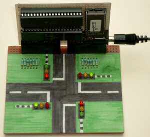 The second example is a simple traffic light system.
It represents a normal cross-road, where road A crosses road B.
Four traffic lights regulate the traffic.
It took me longer to paint the roads on the PCB shown in the picture than to make the program work.
The interface is very simple and consists of just 12 LED's and their series resistors to build the 4 traffic lights. No inputs are needed for this simple example.
Not only the interface is simple, the program isn't very difficult either.
After initialization it starts reading a state table from top to bottom.
Every entry in this state table contains 5 bytes.
The first byte represents the time that this particular state should last, i.e. the time in which the light pattern is shown on the traffic lights.
This time is measured in units of about 0.1 seconds.
The next two bytes hold the state of the two traffic lights on road A, while the last two bytes hold the state of the lights on road B.
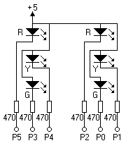 Why 2 bytes per set of lights?
Simple, to easily enable flashing of some of the lights if necessary.
The first byte of the pair represents the light pattern when the flashing light should be on, while the second byte of the pair represents the pattern when it must be off.
As soon as the program finds the first byte of the record to be 0 means that the state table has reached its end.
Then the next two bytes hold the location in the state table to jump to in order to start all over again.
The program listed below mimics a Dutch traffic light system. Many other systems exist though. You may change the state table to make the traffic lights work the way you're familiar with.
For the clever ones among you, you can even add some pedestrian crossing lights to the original design too. Add a few push buttons so the pedestrians can request a green light on demand.
;------------------------------------------------------------------------
;
;  TL_NL.ASM
;
;  Author: San Bergmans
;          www.sbprojects.net
;
;  Created for the 6802 Nano Computer at 15-11-1993
;
;  This program demonstrates the traffic lights on a normal intersection
;  The lights on the main road show green simultaneously, while the
;  lights from the side road show green in turn.
;
;------------------------------------------------------------------------

             .CR    6800                Select cross overlay
             .OR    $F000
             .TF    TL_NL.HEX,INT       Specify target file

;------------------------------------------------------------------------
;  Declaration of constants
;------------------------------------------------------------------------

TABLE_PNTR   .EQ    $00,01              Pointer in state table
LIGHTS_A1    .EQ    $02                 Status for lights on road A
LIGHTS_A2    .EQ    $03
LIGHTS_B1    .EQ    $04                 Status for lights on road B
LIGHTS_B2    .EQ    $05

PIA_A        .EQ    $0080               Pia data register A
PIA_B        .EQ    $0081               Pia data register B
CON_A        .EQ    $0082               Pia control register A
CON_B        .EQ    $0083               Pia control register B

DELAY        .EQ    12500               Delay counter for approx. 100ms.

;------------------------------------------------------------------------
;  Reset and initialisation
;------------------------------------------------------------------------

RESET        LDS    #$007F              Reset stack pointer
             LDAA   #%0000.0100         Initialise PIA ports
             STAA   CON_A
             STAA   CON_B
             LDAA   #%0011.1111         b0..b5 are outputs b6+b7 are
             STAA   PIA_A                inputs for both PIA ports
             STAA   PIA_B
             CLRB
             STAB   CON_A
             STAB   CON_B
             STAA   PIA_A
             STAA   PIA_B
             LDAA   #%0000.0100         Select data registers again
             STAA   CON_A
             STAA   CON_B

             LDX    #STATE_TABLE        Load start address of
             STX    TABLE_PNTR           state table

;------------------------------------------------------------------------
;  Main program loop
;------------------------------------------------------------------------

MAIN         LDX    TABLE_PNTR          Load state table pointer
             LDAB   0,X                 Get delay time from table
             BNE    .NOT_END            Not the end of the table yet!
             LDAA   1,X                 Restart the table (take reload
             STAA   TABLE_PNTR           value from the end of the table)
             LDAA   2,X
             STAA   TABLE_PNTR+1
             LDX    TABLE_PNTR
             LDAB   0,X                 Get new delay time again

.NOT_END     INX                        Read light patterns for Road A
             LDAA   0,X
             STAA   LIGHTS_A1           Keep light pattern in RAM
             INX
             LDAA   0,X
             STAA   LIGHTS_A2
             INX                        Read light patterns for Road B
             LDAA   0,X
             STAA   LIGHTS_B1           Keep light pattern in RAM
             INX
             LDAA   0,X
             STAA   LIGHTS_B2
             INX                        Save the incremented pointer
             STX    TABLE_PNTR
             BSR    WAIT                Show this pattern for a while
             BRA    MAIN                Repeat the main loop for ever

;------------------------------------------------------------------------
;  Wait until the delay is over (includes flashing of lights).
;------------------------------------------------------------------------

WAIT         BITB   #%0000.0100         What is the current flash state?
             BEQ    .LIGHTS_ON          State 1! Lights are always on!
             LDAA   LIGHTS_A2           Copy 2nd status to the outputs
             STAA   PIA_A
             LDAA   LIGHTS_B2
             STAA   PIA_B
             BRA    .DEC_WAIT

.LIGHTS_ON   LDAA   LIGHTS_A1           Copy 1st status to the outputs
             STAA   PIA_A
             LDAA   LIGHTS_B1
             STAA   PIA_B

.DEC_WAIT    BSR    DELAY_100MS         Delay about 100 milli seconds
             DECB                       Decrement total delay counter
             BNE    WAIT                Not 0 yet! Repeat delay loop
             RTS

;------------------------------------------------------------------------
;  Wait 0.1s routine
;------------------------------------------------------------------------

DELAY_100MS  LDX    #DELAY              Set delay counter and count down
.LOOP        DEX                         to 0
             BNE    .LOOP               Not 0 yet!
             RTS

;------------------------------------------------------------------------
;  State table
;
;  5 Bytes per record
;  Byte 1: Time of this state (x 0.1s)
;  Byte 2: b7 = not used
;          b6 = not used
;          b5 = red light A1 (0=light on)
;          b4 = yellow light A1
;          b3 = green licht A1
;          b2 = red light A0
;          b1 = yellow light A0
;          b0 = green light A0
;  Byte 3: same as byte 1, now for the off state during flashing
;  Byte 4: Same as Byte 2, but this time for road B
;  Byte 5: Same is Byte 3, but this time for road B
;
;  End of table if first record byte = 0. Then the next 2 bytes indicate
;  the loop address in the state table.
;------------------------------------------------------------------------

STATE_TABLE  ;      show during 10 seconds all yellow flashing lights
             .DA    #100                100x 0.1 seconds
             .DA    #%00.101.101        Road A Yellow flashing
             .DA    #%00.111.111
             .DA    #%00.101.101        Road B Yellow flashing
             .DA    #%00.111.111

             ;      show 5 seconds all red lights
             .DA    #50                 50x 0.1 seconds
             .DA    #%00.011.011        Road A all Red
             .DA    #%00.011.011
             .DA    #%00.011.011        Road B all Red
             .DA    #%00.011.011

.LOOP        ;      road A green, road B red, 8 seconds
             .DA    #80
             .DA    #%00.110.110        Road A all Green
             .DA    #%00.110.110
             .DA    #%00.011.011        Road B all Red
             .DA    #%00.011.011

             ;      road A yellow, road B red, 2.5 seconds
             .DA    #25
             .DA    #%00.101.101        Road A all Yellow
             .DA    #%00.101.101
             .DA    #%00.011.011        Road B all Red
             .DA    #%00.011.011

             ;      all roads red for 1 second
             .DA    #10
             .DA    #%00.011.011        Road A all Red
             .DA    #%00.011.011
             .DA    #%00.011.011        Road B all Red
             .DA    #%00.011.011

             ;      road A red, road B0 green, road B1 red, 8 seconds
             .DA    #80
             .DA    #%00.011.011        Road A all Red
             .DA    #%00.011.011
             .DA    #%00.011.110        Road B0 Green, B1 Red
             .DA    #%00.011.110

             ;      road A red, road B0 yellow, road B1 red, 2.5 seconds
             .DA    #25
             .DA    #%00.011.011        Road A all Red
             .DA    #%00.011.011
             .DA    #%00.011.101        Road B0 Yellow, B1 Red
             .DA    #%00.011.101

             ;      all roads red for 1 second
             .DA    #10
             .DA    #%00.011.011        Road A all Red
             .DA    #%00.011.011
             .DA    #%00.011.011        Road B all Red
             .DA    #%00.011.011

             ;      road A red, road B1 green, road B0 red, 8 seconds
             .DA    #80
             .DA    #%00.011.011        Road A all Red
             .DA    #%00.011.011
             .DA    #%00.110.011        Road B0 Red, B1 Green
             .DA    #%00.110.011

             ;      road A red, road B1 yellow, weg B0 red, 2.5 seconds
             .DA    #25
             .DA    #%00.011.011        Road A all Red
             .DA    #%00.011.011
             .DA    #%00.101.011        Road B0 Red, B1 Yellow
             .DA    #%00.101.011

             ;      all roads red for 1 second
             .DA    #10
             .DA    #%00.011.011        Road A all Red
             .DA    #%00.011.011
             .DA    #%00.011.011        Road B all Red
             .DA    #%00.011.011

             ;      end of table and next address in table to contionue
             .DA    #%00.000.000,.LOOP

;------------------------------------------------------------------------
;  Interrupt and reset vectors
;------------------------------------------------------------------------

             .NO    $FFF8,$FF
             .DA    RESET               IRQ (not used)
             .DA    RESET               SWI (not used)
             .DA    RESET               NMI (not used)
             .DA    RESET               Reset

             .LI    OFF
Please note: The program target file starts at address $F000. Set the offset address of your Eprom programmer to $F000 before burning. If you can't set the offset address in your Eprom programmer you can always change the target file format to plain binary.
Conclusion
Hopefully I have given you enough inspiration with this project to develop some applications of your own. I can think of many more applications using this 6802 Nano Computer. Below you can find a small list of possible applications:
- Clock (with date and automatic daylight savings switching)
- Thermometer/thermostat
- Data logger
- Calculator
- Model railway automation
- Robotics
- Remote control applications
- Intelligent battery charger
- Experiments with I2C components
- Experiments with LCD displays
- Experiments with stepper motors
- Experiments with servo actuators
This is only a small list of things you could do with the 6802 Nano Computer. You may even combine functions into one complete project.
One last request to those students among you who enter my projects unchanged: "What grade did I get from your mentor?"
PS: Don't forget to enter your own name in the program before submitting my project ;-)
