M-3850 USB Interface

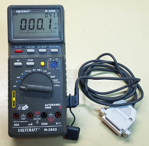
Look here, what I have found while rummaging through some of my boxes, filled with noble electronics junk. It's a serial interface cable for my Voltcraft (Metex) M-3850 multi meter. Judging by the DB-25 connector this thing can truly be considered to be antique by now. Wouldn't it be nice to make it connect to a USB port instead? It certainly would make a nice, short, quick, in-between project.
Serial Interface
 The serial interface of the M-3850 is electrically isolated from the potentially dangerous input voltages by 2 opto-couplers.
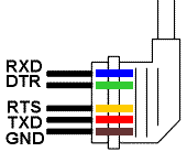
Adding two resistors and 5 wires and you've got the entire serial interface.
These 5 wires go directly to the DB-25 connector.
The DTS and RTS lines of the serial interface are used to provide "power" to the circuit.
DTS supplies the +12V, while RTS supplies the -12V.
Fortunately we can't be bothered about these signals.
We can simply drive everything from 5V, supplied by the USB interface.
USB To Serial Converter
 For this purpose I use a ready made converter from Banggood.
I couldn't find the exact same one I've bought anymore, but there are plenty of other modules to choose from, even smaller ones than the one I've got.
Choose a module which has a selectable 5V or 3V3 I/O level.
The interface runs on 5V logic levels.
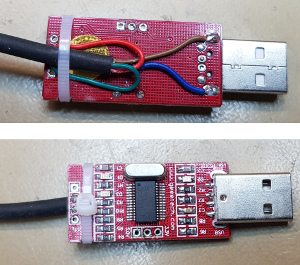
All the header pins were removed from the USB serial module to make it more compact.
A jumper wire is used to select the 5V I/O level.
Four of the 5 wires, which originally were soldered to the DB-25 connector, are soldered to the PCB.
The yellow wire has no purpose any more and can be cut short.
The blue and brown wires are both soldered to the GND plane of the USB serial interface.
The red wire is soldered to the TxD terminal of the desoldered header, while the green wire is soldered to the RxD terminal.
And that is basically all that there's to it.
I have filed a few small indents into the side of the board, which are used to hold a cable tie, which straps the cable down to the board.
A 1" shrink wrap sleeve is used as a poor man's housing for the PCB.
Maybe, someday, I will be able to 3D print a more elegant housing for the PCB.
But for now it will do.
Communicating With The M-3850
Communication is done at a whopping 1200 baud, with No parity, 7 data bits and 2 stop bits. Press the instrument's function key several times until you see the "COM" annunciator in the display. Please note that other functions, like REL, MIN, MAX are not possible while communicating with a computer.
Messages from the multi meter always consist of 14 characters, no matter what function or range the meter is in. Here are some examples:
DC  000.1  mV
DC  159.0  mV
DC  12.28   V
DC -12.28   V
DC  26.66  mA
DC  03.25   A
OH   O.L MOhm
OH  14.53KOhm
DI    OL   mV
DI    OL   mV
DI    OL   mV
DI    OL   mV
DI    OL   mV
DI  0284   mV DI  0286   mV DI 0285   mV
FR  2.222 KHz
CA  1.208  nF
HF  0089
TM  0022    C TM  0022    C TM  0022    C TM  0022    C
TM  0021    C TM  0021    C TM  0021    C TM  0021    C
LO   rdy
Bugs
The M-3850 is a battery powered device, which switches off after a while to preserve battery power.
Why does it also switch off while the instrument is in the COM mode?
I consider that to be a stupid bug in the software.
Alas, it's the way it is, we'll have to live with it.
You can occasionally press the back light button to keep the meter from falling asleep.
This isn't of much help of course if you want to use the meter for long duration, unattended logging.
Each output string consists of 14 characters, the last one being a CR character, regardless of the meter's function.
Except for the diode test function and both temperature functions, which don't transmit the closing CR character.
As long as the diode function displays Overload everything is OK.
Any other value will be printed on one single line, without any CR characters.
At least, that's what my meter does.

