Fluke 8030A
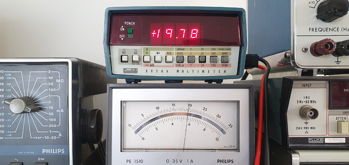
This one again is a trip down memory lane. I have seen this type of multimeter being built in Tilburg, back in 1979/1980. What I particularly can remember is the peculiar design. A relatively small box, inputs on the side, extendable sun cap and especially the way in which the PCB is folded together. I distinctly remember some broken PCBs in the test room, where the transistors which drive the DC/DC converter had exploded, leaving just a few pins sticking out of the PCB. Apparently this happened sometimes when switched on for the very first time. It had something to do with the matching of both transistors, which drive the DC/DC converter.
In my mind I can still see those pins sticking out. But what I can’t remember is where I’ve got this instrument from. I still do know some people who have worked for Fluke back then. Maybe one of them donated this instrument to me. It is quite insensitive of me not to remember who gave it to me. But that happens when you’re running out of memory.
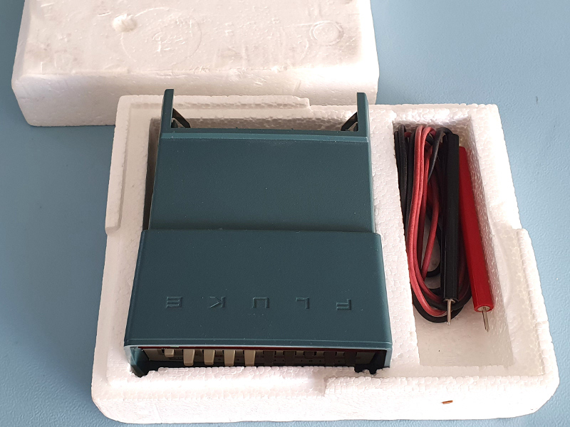 Brand new but sadly no battery cover
 Nice instrument, horrible test leads
Anyway, the instrument appears to be brand new. Not a scratch mark on it. Packed in the original styrofoam box, including some dodgy test leads. I really like the old Fluke equipment, but obviously Fluke had still a lot to learn about making proper test leads. What was missing though was the cardboard outer box, and more importantly, the battery cover. Without a battery cover it was difficult to use the instrument safely. That’s why it has stayed in its box until late 2020.
Late 2020 I found a second hand Fluke 8030A on a Dutch auction site.
I didn’t really care about the state of the instrument, I was mainly interested in the battery cover.
Fortunately I was able to buy that instrument for a reasonable price.
OK, technically speaking the price was not that low considering I was only interested in the battery cover.
But hey, I received a whole lot of spare parts for the same price.
The second hand instrument did have some use marks on it.
Decals were missing or hanging loose.
The Ampere input was a bit worn out.
And the instrument didn’t work properly on all scales.
It will need some love and attention to get it to an operational state again if I want to.
Maybe I will do that in the distant future.
Then I will have two working models of the Fluke 8030A, again with one missing battery cover.
 It took me some time to be able start working on bringing my brand new and now complete instrument back to operational condition.
Moving house and the associated building/remodeling of it didn’t help to speed up the process either.
It’s not that the instrument needed too much to work on.
After all, it was brand new.
I only had to create a power source for it and check its operations.
I didn’t like the idea of powering the instrument from a wall adapter.
I wanted to make it battery powered, just like it was intended.
I wonder, would the Fluke 8030A have been the world’s first portable digital multimeter?
My second hand instrument had a 1975 QA stamp on it, so it could well have been the first.
Some Facts
| Manufacturer | Fluke |
| Years in production | ±1975 … ±1980 |
| My brand new 8030A | 1978 |
| My second hand 8030A | 1975 |
| DC Voltage ranges | ±199.9mV, ±1.999V, ±19.99V, ±199.9V, ±1100V All at 0.1% of reading and 10MΩ |
| AC Voltage ranges | 199.9mV, 1.999V, 19.99V, 199.9V, 750V True RMS AC with a 1…3 crest factor ±0.5% of reading on all ranges up to 1kHz Imput impedance 10MΩ plus <100pF |
| DC current ranges | ±199.9µA, ±1.999mA, ± 19.99mA, ±199.9mA, ±1999mA ±0.35% of reading Burden voltage <0.25V, <0.7V on 1999mA range |
| AC current ranges | 199.9µA, 1.999mA, 19.99mA, 199.9mA, 1999mA ±1% of reading up to 5kHz Burden voltage <0.25V RMS, <0.7V RMS on 1999mA range True RMS AC+DC with crest factor 1.…3 |
| Resistance | 199.9Ω, 1.999kΩ, 19.99kΩ, 199.9kΩ, 1999kΩ ±0.4% of reading (No 20MΩ range) |
| Power supply | 4x C-Cell (for 10 hours of operation 6V DC power supply (center negative) |
| Size h x l x w | 64mm x 145mm x 124mm |
Although the QA stamp on my second hand donor instrument shows it was manufactured in 1975 I assume the internals were replaced at some point because the date stamps on components indicate that it could not have been manufactured before 1979.
Battery Modification
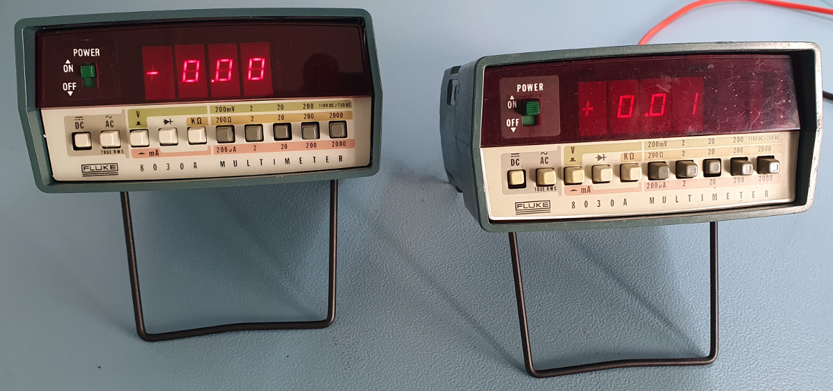 Look mommy, no wires (on the left instrument)
Powering the instrument through a 6V wall adapter would be the easiest solution.
When you do that, keep in mind that the power connector is center negative!
And the barrel connector is recessed rather deep, so you might have to modify the barrel plug a bit to make it fit.
Keep in mind that the barrel plug is about 6V above the voltage level applied ot the negative input terminal!
Thus when you directly connect the input to the mains power, the barrel plug may be at some 230V above ground level.
Safety wasn’t so much of an issue back in the days.
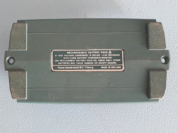 The rear of the battery cover
 The inside of the battery cover
I would rather prefer to power the instrument with batteries.
Normal alkaline batteries can power the device up to some 10 hours.
Which is not very convenient, and rather expensive.
On top of that normal batteries always expose the instrument to a possible battery leakage.
Rechargeable batteries are a better solution.
The instrument was designed to be powered by 4 C-cell NiCd batteries.
NiCd batteries have a lower capacity than alkaline batteries.
According to the manual the operation time would be around 8 hours.
The batteries can be charged by a wall adapter connected to the power input of the instrument.
A pin in the battery cover can disconnect the charger from the battery compartment in case you use alkaline batteries.
It would be a very bad idea to charge alkaline batteries.
However I’ve noticed that my donor instrument doesn’t have this switch.
Instead of that switch a wire bridge is installed, which connects the power input to the batteries at all times.
Therefore it is not intended to be powered by the wall adapter while fitted with alkaline batteries.
So NiCd batteries are an option. However those are soooo nineteen eighties. It would be much more appropriate to fit the instrument with more modern LiION batteries. This proved to be much easier than expected.
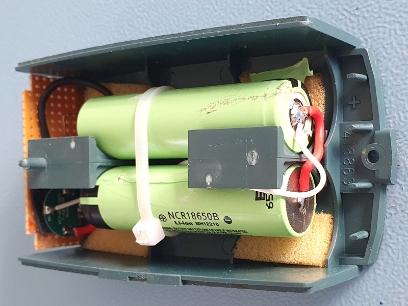 LiION batteries easily fitted
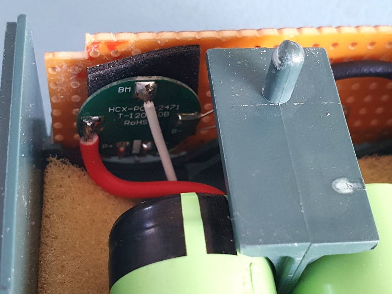 The BMS is also easily mounted somewhere
Two 18650 batteries, with a total capacity of 3Ah, will fit nicely in the battery cover. A tierap is all that’s needed to secure them in place, clamping them against the plastic bridges in the middle of the battery cover. A piece of strip board on one end of the battery cover can now make contact to the battery terminals of the instrument. A simple 2S BMS from China completes the protection circuit for the batteries. Such a BMS protects the batteries from over charge/discharge, allowing the batteries to serve you for a long time.
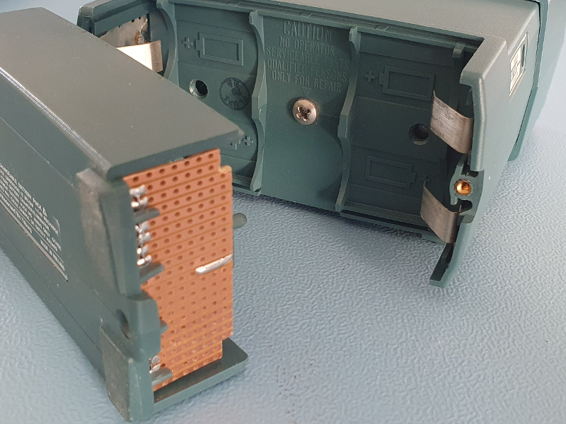 Battery cover half open
 Battery cover fitted into the instrument
Charging the batteries is simply a matter of connecting a lab power supply to the positive and negative terminals of the removed battery pack. This can be done with two alligator clips. Set the power supply to 8V, with the current limited to 1A. That way the batteries will safely charge to full capacity within about 3 hours. The batteries are full when the current has dropped to about 200mA or so. The BMS protects the batteries from over charging in case you forget to disconnect the batteries from the power supply.
The instrument will happily run about 12 hours on a set of fully charged batteries.
And you don’t have to worry too much about the self discharge of the batteries, because LiION batteries are known to have low self discharge characteristics.
You can always measure the battery voltage by switching the instrument to the 20V DC range and sticking the positive probe in the small hole labeled Btry Test at the bottom of the instrument.
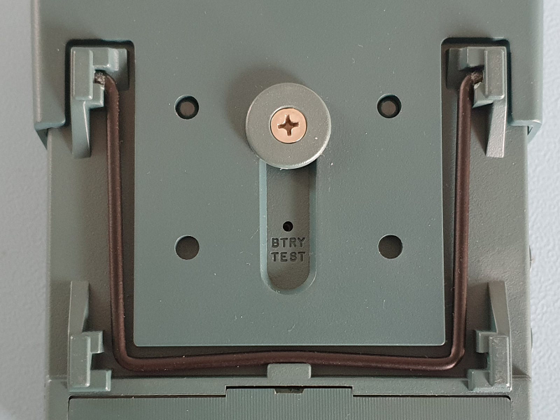 Battery test hole
 I have completely removed the fuse
I have removed the fuse which was placed between the opposite battery connectors in the battery compartment. These connectors are now floating, making it safe to install the battery cover upside down. It won’t work, but now it doesn’t blow up the fuse if I was to insert the battery cover upside down.
Be very careful with LiION batteries. They look so harmless. I’ve salvaged mine from a larger battery pack. All cells were glued together for better mechanical stability. While dismantling such a pack it is very easy to damage the plastic sleeve of the cells. Who needs these sleeves anyway. I don’t. That is, I don’t as long as the batteries are safely fastened inside the battery compartment. But don’t let them touch their bodies together when you’ve connected them in series! One of them will be shorted that way. Trust me, I’ve been there, done that! No harm was done, but for the final installation I’ve used two fresh cells from the pack, just to be on the safe side.
And one more warning. Be careful not to overheat the cells while soldering the wires to them. Set your soldering iron to the highest temperature and be quick to solder. That way the heat doesn’t have time to conduct to the chemicals inside the cell. I never apply heat for more than 5 seconds, and I have never damaged any cells that way.
A Look Inside
Taking the instrument apart is fairly easy. Start by removing the Ampere input jack, which holds the fuse. You’ll have a hard time removing the case if you don’t. Then remove the single screw in the center of the battery compartment.
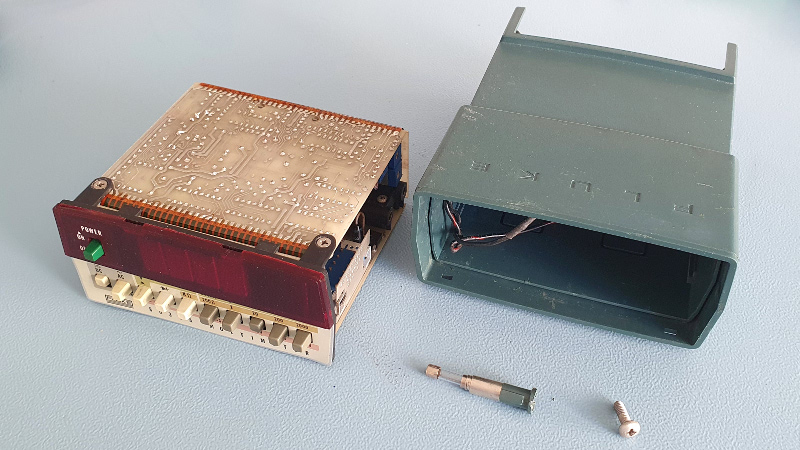 Don't forget to remove the Ampere input jack first
Now you can easily slide the instrument out of the case. Two wires run from the PCB to the battery contacts. These wires are connected to the PCB by single pole connectors. Simply pull them away from the PCB to completely separate the PCB from the case. Remember to put the wire with the red marking to the + connector on the PCB again when you reassemble the instrument. The black wire goes on the remaining connector of course.
 click on the image to see it in the original resolution
I have taken the donor instrument apart and unfolded the PCBs in order to take this picture. I don’t dare to do that with my brand new instrument because the flex cables may have become a bit brittle after some 40 years. I hate to damage it just before I’m finally able to start using the damn thing. Luckily the donor also survived the photo shoot.
There weren’t too many of these PCBs laying around in the factory back in 1980, but I distinctly remember the peculiar build of this instrument. Especially the area around the DC-DC converter, with the exploded transistors. This unit however is in perfectly good order.
 Signals seen on pin 1 and pin 4 of the DC-DC transformer"
I have seen pictures of the 8030A where the DC-DC converter’s transformer was fully potted, probably to reduce the sound it produces. The DC-DC converter runs at about 9kHz, which can be clearly audible, especially for young people. Even I, at my not so young age, can still hear it sometimes especially when the display is blinking due to an overload condition. If it bothers me I can always decide to dip mine in some potting material someday. Or I can wait another 10 years, I’m sure I won’t be able to hear 9kHz anymore then.
The left board in the picture contains the range and function switches and most of the input attenuators and protection circuitry.
The 8030A uses the same Analog to Digital conversion circuitry as its ancestor the 8000A.
Despite its smaller size the 8030A has some large improvements over the 8000A.
The biggest improvement can be found around the input protection, which was basically non-existent in the 8000A.
The 8030A has some Varistors, the five red components on the top right hand corner of the left PCB, which start conducting when the voltage applied to them exceeds some 390V or so.
There are no spark gap cut outs in the PCB like modern instruments tend to have.
But it’s better than no protection at all.
The big brown disk component on the top is the AC coupling capacitor.
The center board contains the true RMS converter, which is also an improvement over the 8000A, which simply had a precision rectifier.
The right board (not counting the display board) contains the Analog to Digital converter and the DC-DC converter.
The metal part on the top is a shield which fits over the center PCB.
It is also required to fasten the one screw which holds the instrument together.
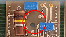 This is where the battery disconnect switch (S12) was supposed to be fitted.
On this model the switch is replaced by a wire bridge at the back of the PCB.
Thus the power input connector is always connected to the battery terminals, which means that it is dangerous to use this instrument with an AC power adapter while alkaline batteries are installed.
Now I understand why the user manual constantly mentions a battery charger/eliminator when it is referring to the wall adapter!
You can charge rechargeable batteries with it, or you can eliminate normal batteries with it.
I hope they don’t create a big mess while being eliminated.
How Is The Calibration?
And now, for the most important question to ask: Is it still within specs, after sitting in its box for over 40 years? I can only compare the Fluke 8030A with an instrument with better specs. Let's see how far we can check its performance.
| Input | Reading | Specified accuracy | Actual accuracy | Result |
| 0.000V DC | +0.1mV DC | OK | ||
| +190.0mV DC | +189.8mV DC | ±0.1% | -0.1% | OK |
| -190.0mV DC | -189.9mV DC | ±0.1% | -0.05% | OK |
| +1.900V DC | +1.899V DC | ±0.1% | -0.05% | OK |
| -1.900V DC | -1.899V DC | ±0.1% | -0.05% | OK |
| +19.00V DC | +18.98V DC | ±0.1% | -0.1% | OK |
| -19.00V DC | -18.99V DC | ±0.1% | -0.05% | OK |
| +190.0mA DC | +189.5mA DC | ±0.35% | -0.26% | OK |
| -190.0mA DC | -189.8mA DC | ±0.35% | -0.1% | OK |
| +1.900A DC | +1898mA DC | ±0.35% | -0.1% | OK |
| -1.900A DC | -1899mA DC | ±0.35% | -0.05% | OK |
| 0.000V AC | 1.1mV AC | OK | ||
| 190mV 50Hz Sine | 189.9mV AC | ±0.5% | -0.05% | OK |
| 190mV 1kHz Sine | 189.7mV AC | ±0.5% | -0.16% | OK |
| 190mV 10kHz Sine | 188.9mV AC | ±2% | -0.6% | OK |
| 1.9V 50Hz Sine | 1.899V AC | ±0.5% | -0.05% | OK |
| 1.9V 1kHz Sine | 1.898V AC | ±0.5% | -0.1% | OK |
| 1.9V 10kHz Sine | 1.891V AC | ±2% | -0.47% | OK |
| 190mV 50Hz Square | 189.8mV AC | ±0.5% | -0.1% | OK |
| 190mV 1kHz Square | 189.3mV AC | ±0.5% | -0.37% | OK |
| 190mV 10kHz Square | 186.5mV AC | ±2% | -1.88% | OK |
| 1.9V 50Hz Square | 1.896V AC | ±0.5% | -0.2% | OK |
| 1.9V 1kHz Square | 1.888V AC | ±0.5% | -0.6% | OK |
| 1.9V 10kHz Suare | 1.864V AC | ±2% | -1.9% | OK |
| 90.0Ω | 90.0Ω | ±0.4% | 0.0% | OK |
| 900Ω | 899Ω | ±0.4% | -0.1% | OK |
| 9.00kΩ | 9.03kΩ | ±0.4% | +0.3% | OK |
| 90.0kΩ | 89.9kΩ | ±0.4% | -0.1% | OK |
| 900kΩ | 897kΩ | ±0.6% | -0.3% | OK |
Splendid!
I'm not going to try to improve the calibration.
I'm afraid I'm only going to make it worse.
You'll never know with potmeters which haven't moved in over 40 years.
Due to the lack of a calibrator I could not check all ranges.
But judging by the results that I could check I'm quite confident that the instrument is still within specs on all ranges.
I'm very happy with this instrument. And even though I have more convenient (portable) instruments to work with, I'm sure I'll grab this one whenever I can. Just to make up for lost times I guess, compensate for the years it has spent in its box, doing nothing.
